


TE Series Digital Solid State Soft Starters 18 – 1250A
87
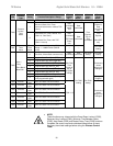
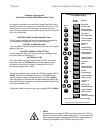
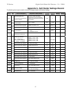
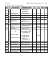
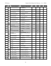
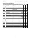
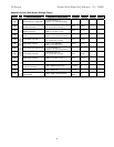
Appendix 6 - Soft Starter Settings Record
The following chart may be used to record the changes made to the factory settings.
Fn # Group Function Description Adjustment / Display Range
Setting
Increments
Factory
Setting
Setting Setting
F001
Motor and Overload Info.
Motor Nameplate FLA
FLA must be programmed for
starter to function.
50-100% of Max Amp Rating.
Upper limit of range automatically
adjusts downward as Service factor
is increased.
1 amp 0
F002
Motor Nameplate
Service Factor
1.00 - 1.30 SF 0.05 1.0 SF
F003 Overload Class During Start NEMA / UL Class 5 - 20 5 Class 10
F004 Overload Class During Run NEMA / UL Class 5 - 30 5 Class 10
F005 Overload Reset
0 = Manual
1 = Auto
2 = Disabled Overload
1
0
(Manual)
F006-9
Reserved for factory use
F010
Starting and Stopping Modes
Ramp Type Selection
VR = Voltage Ramp
CR = Current PID Ramp
1 = Ramp 1, 2 = Ramp 2
Setting 1 = VR1 + VR2
Setting 2 = CR1 + CR2
Setting 3 = VR1 + CR2
Setting 4 = CR1 + VR2
1
1
VR1+VR2
F011 Initial Torque (VR) of Ramp 1 0-100% Line Voltage 1% 60%
F012 Initial Torque (CR) of Ramp 1 0-600% Motor
Current
1% 200%
F013 Accel Ramp Time of Ramp 1 1-120 seconds 1 second
10
seconds
F014 Max Current Limit of Ramp 1 200 - 600% Motor
Current
1% 350%
F015 Initial Torque (VR) of Ramp 2 0-100% Line Voltage 1% 60%
F016 Initial Torque (CR) of Ramp 2 0-600% Motor
Current
1% 200%
F017 Accel Ramp Time of Ramp 2 1-120 seconds 1 second
10
seconds
F018 Max Current Limit of Ramp 2 200 - 600% Motor
Current
1% 350%
F019
Jog Modes
Voltage Jog 5 – 100% Line Voltage 1% 50%
F020 Time of Voltage Jog 1 – 20 Seconds 1 second
10
seconds
F021 Current Jog 100 – 500% Motor
Current 1% 150%
F022
Kick
Mode
Kick Start Voltage
0 = Disabled, or
10 - 100% Line Voltage
1%
0
Disabled
F023 Kick Start Time 0.1 - 2 Seconds 0.1second 0.8 sec