


TE Series Digital Solid State Soft Starters 18 – 1250A
53
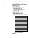
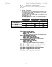
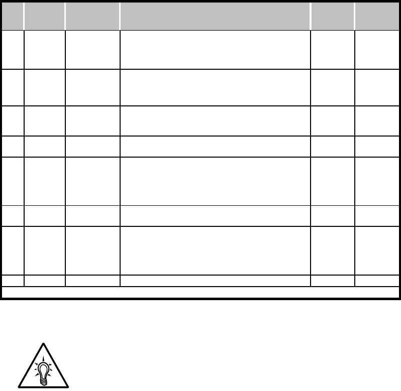
5.6.9.a (continued) Function 51: Internal Protection Features
NOTE:
To restore all settings back to the factory default, enter a value of
127. If you see a numeric value other than the default value of 127,
one or more features has already been altered. If you do not know
which one or ones are changed, the simplest thing to do is
determine what combination of settings you want now, and subtract
from 127 then enter that number to accomplish it.
Example: F051 reads a numeric value of 109, meaning that something
has been changed, but you don’t know what. By subtracting 109
from 127, you have a value of 18 remaining, and since 18 does not
represent a single bit, it means that some combination has been
used. Subtract the largest represented bit, i.e. bit #4 (value of 16),
which leaves a value of 2, representing bit #1. So in this example,
the Shunt Trip feature had been turned off, and the Expected Phase
Sequence had been changed to A-C-B.
If you do not wish to bother with what the previous settings were,
simply decide which features you now want to be turned on and
come up with a new numeric value to enter. For instance if you want
all features on, but you need phase rotation to be A-C-B (bit #1),
then simple subtract a value of 2 from 127, and enter 125 into F051.
Bit
#
Fault
Display
Code
Protection
Function
Description
Default
Bit
Setting
Decimal
Value
0
rtd *
Phase
Rotation
Trip
Phase Rotation protection.
Phase rotation must match selection in Bit #2
below. Setting to Off (0) will make the TE
insensitive for use behind a reversing contactor
1 (On) 1
1 ABC
Expected
Phase
Sequence
2 = A-B-C Phase Rotation Sequence Only
0 = A-C-B Phase Rotation Sequence Only
1
(A-B-C
Rotation)
2
2
PLa or
PLc*
Phase
Current
Loss
Phase Current Loss, any phase current reading is
less than 20% of unit max amp rating after 3
seconds from Start command.
1 (On) 4
3 SS*
Shorted
SCR
At least one SCR has shorted; there is no voltage
drop across the SCR phase assembly.
1 (On) 8
4 ST*
Shunt
Trip
Shunt Trip of the main Circuit Breaker or Isolation
Contactor (if provided and wired to an Aux. relay
in F060-F061)). 2 or more SCRs have shorted in
opposing phases so current was flowing to the
motor while the TE was in the Off state.
1 (On) 16
5 PTc*
PTC Input
Trip
PTC Trip function. This can be disabled so that a
jumper is not required across the PTC inputs.
1 (On) 32
6
PLd or
n3Ph
Line Phase
Loss Trip
Protection against loss of input line voltage.
Disable when using an In-Line Isolation Contactor
or any other system that normally removes line
power from the starter. Resets automatically when
line voltage returns.
1 (On)
64
7 --- Reserved Reserved for factory use 0 (Off) 128
* = Operating Mode designation. See Fault Code List for description.
Table 5.6.9.a: Function 51 table of Hardware Protection Features