


TE Series Digital Solid State Soft Starters 18 – 1250A
24
Display
Press
Key...
Shows...
Means...
Phase A
Current
Phase B
Current
Phase C
Current
Remaining
Thermal Capacity
Ground Fault
Current
Process Timer
Remaining Time
0120
.
0121
0120
H0 8 3
G0 0 2
0060
13.. 30
Time Clock
Time Base
Loop Back to
Phase A Current
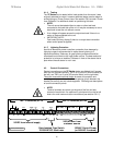
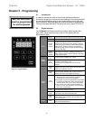
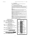
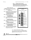
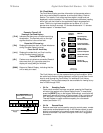
Figure 5.3.1: Reading the Status Display
0120
.
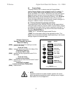
5.3 Display Modes
There are three modes of display: the Status Display Mode, the
Program Mode, and the Fault Mode.
5.3.1 Status Display Mode (Default Display)
The Status Display Mode displays seven “screens” of information. Motor
Currents (3 phases), Remaining Thermal Capacity, Ground Current,
Remaining Time on the Process Timer, and Time Base of the Time
Clock Controller. This is also the entry screen for going into the Program
Mode.
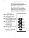
Status mode:
[0000.] The initial display on power up is four digits and the decimal.
This indicates the motor current for Phase A of the motor.
[0000] Scroll UP to display four digits only (no decimal). This indicates
the motor current for Phase B. While viewing Phase B, press the UP
arrow again to view Phase C current.
[G000] Scroll UP to display the “G”. This indicates that this value is the
current flowing to ground on the motor leads.
[H000] Scroll UP to display the “H”. This indicates that this value is the
remaining thermal capacity percentage of the motor (i.e. H070 = 70%
remaining thermal capacity)
[0000] Scroll UP again to display the Process Batch Timer (described in
Section 5.6.7). If this entire screen is flashing, the Timer is active.
[00.00] Scroll UP to display two pairs of digits separated by a point: This
indicates the time base of the Time Clock Controller (described in
section 5.6.7). If the display shows [00.00], the TCC is not enabled. This
follows the time settings in F075 – F080.
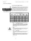
Example: Figure 5.3.1
Reading the Status Display
[0120.] Indicates Phase A is drawing 120 amps.
Press the UP arrow
[0121] Indicates Phase B is drawing 121 amps.
NOTE: Decimal points are not present in the
readouts for Phases B and C.
Press the UP arrow
[0120] Indicates Phase C is drawing 120 amps.
Press the UP arrow
[G002] Indicates that there are 2 amps of current flowing
to ground in the motor leads or motor.
Press the UP arrow
[H083] Indicates the motor has 83% of its thermal capacity
remaining (H = Heat).
Press the UP arrow
[0060] Indicates there is 60 minutes remaining on the
Process Timer. If flashing, the timer is active.
Press the UP arrow
[13.30] Indicates the time base of the Time Clock
Controller is 1:30 PM (24hr time). If flashing, the
time clock is active and pending the next event.
Press the UP arrow
[0120.] Loop back to Phase A current indication