


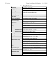
TE Series Digital Solid State Soft Starters 18 – 1250A
5
Chapter 2 - Installation
2.1 Receiving and Unpacking
Upon receipt of the product, you should immediately do the following:
Carefully unpack the unit from the shipping carton and inspect it for
shipping damage (if damaged, notify the freight carrier and file a
claim within 15 days of receipt).
Verify that the model number on the unit matches your purchase
order.
Confirm that the ratings sticker on the unit matches or is greater
than the motor’s HP and current rating.
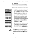
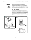
2.2 Choosing a Location
Proper location of the TE Series is necessary to achieve specified
performance and normal operation lifetime. The TE Series should
always be installed in an area where the following conditions exist:
Ambient operating temperature:
Panel (open chassis) unit: 0 to 50°C (32 to 122°F)
Enclosed unit: 0 to 40°C (32 to 104°F)
Protected from rain, moisture and direct sun.
Humidity: 5 to 95% non-condensing
Free from metallic particles, conductive dust and corrosive gas
Free from excessive vibration (below 0.5G)
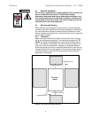
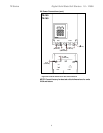
Open panel units must be mounted in the appropriate type of
enclosure. Enclosure size and type must be suitable to dissipate
heat generated by the soft starter and any other components
mounted inside with it.
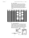
Units with –BP Bypass Contactors produce less heat than units
without. Throughout all sizes, maximum heat dissipation of the
TE…-BP Series electronics, contactor coils and fans is less than
50W.
Units without the –BP Bypass Contactor (optional on 210A and
above), must have ventilation adequate to account for heat
dissipation of the SCRs. This must be estimated at 4.5 watts per
running load amp. For example, on a 200HP 460V motor with
240FLA, the maximum heat dissipation of a starter w/o bypass will
be 240 x 4.5, or 1080 watts of heat. Enclosure ventilation (or air
conditioning) must be capable of dispersing this amount of heat.
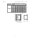
Care should always be taken to maximize the available space
inside of the enclosure. See section 2.5.1 or contact factory for
assistance in sizing enclosures.
2.3 Initial Unit Inspection
Make a complete visual check of the unit for damage that may have
occurred during shipping and handling. Do not attempt to continue
installation or start up the unit if it is damaged.
Check for loose mechanical assemblies or broken wires which may
have occurred during transportation or handling. Loose electrical
connections will increase resistance and cause the unit to function
improperly.
Prior to beginning the installation, verify that the motor and TE
Series unit are rated for the proper amperage and voltage.