


TE Series Digital Solid State Soft Starters 18 – 1250A
20
4.2.6 PTC Thermistor Input
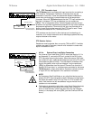
The TE Series starter is provided with input terminals for connecting a
PTC (Positive Temperature Coefficient) Thermistor that may be
imbedded in the motor. These are specialized resistors imbedded in
some motor windings that increase resistance as the temperature
increases. When the TE Series detects that the PTC input resistance is
too high, it initiates a PTC trip, and displays it on the readout as
[ PTc ]. This is independent of the Thermal Register overload current
protection and provides supplemental protection for high motor ambient
temperature applications. Terminals for this input are provided with a
factory jumper that must be removed if the PTC input is used. These
terminals are located on TB1, Terminals 9 and 10.
PTC resistors are also found in other devices such as bearings, air
receivers, oil or coolant reservoirs and air discharge systems that may
require shutdown of the motor.
PTC Resistor Values:
Resistance must be greater than or equal to 750 Ω at 25ºC. If multiple
resistors are used in the motor, the sum of all resistors in series must
equal or exceed this value.
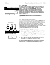
4.2.6.a External Over Load Relay Connection
If an external Over Load Relay (OLR) is used (see Section 3.1.3.c
and Appendix 5), connect the NC aux. contact of the OLR to the
PTC input after removing the jumper. When the external OLR trips,
the contact will open, opening the resistance input to the PTC circuit
(the resistance goes to infinity). This indicates an immediate Over
Load to the starter, which trips and displays it on the readout as
[ PTc ] to differentiate from the internal Thermal Over Load trip. If
multiple OLRs are used, i.e. multiple motors controlled by the same
TE Series starter, simply wire the Aux Contacts in series as shown
in Figure 4.2.6.a. See Appendix 5 for additional information.
NOTE:
An Emergency Stop Push Button or any other field device may be
wired to the PTC input using NC contacts. When the contacts open,
the starter will detect it as a PTC trip. Even if a PTC is used in the
motor, field devices can still be added as long as the total circuit
resistance is not exceeded.
This feature is especially useful when using Decel Control because
it will immediately shut off power to the motor even if Decel is
active. If used this way, instruct the users as to the trip indication
issues (i.e. the display will show [ PTc ] and the Overload LED will
be on).
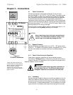
+
N C
JOG
RAM P2
PTC
OPTO
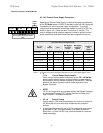
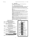
Figure 4.2.6:
PTC Resistor Connection
TB-1
PTC Resistor in Motor
9 10
**
** Remove factory jumper
from Terminals 9 and 10
N C
JOG
RAM P2
PTC
OPTO
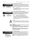
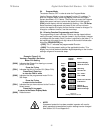
Figure 4.2.6.a:
External Overload Relay(s)
and/or E-Stop PB Connection
TB-1
External OL Relays
OLR 1 OLR 2
9 10
Optional
Emergency Stop PB
**
** Remove factory jumper
from Terminals 9 and 10