


TE Series Digital Solid State Soft Starters 18 – 1250A
16
4.1.4 Testing
The TE Series can be tested with a load smaller than the motor it was
originally selected to control, however additional steps must be taken to
avoid tripping on Phase Current Loss. See section 5.6.9.a under “Phase
Loss Protection” for additional details on performing this task.
NOTE:
The unit cannot be tested without a motor or other test load
connected to the load side of the unit. It may be necessary to use a
load bank to test the unit without a motor.
Line voltage will appear across the output terminals if there is no
motor or load connected to the unit.
IMPORTANT NOTE:
Fault code SSd may display if there is no output load connection
when control power is applied!
4.1.5 Lightning Protection
As with all electronic power controllers, protection from damage by
lightning surges is recommended in areas where lightning is a
significant problem. Stationary air gap lightning arrestors should be
considered and utilized on the input power source. The best method of
protection is to have an Isolation Contactor in front of the starter that is
open when the soft starter is not in use.
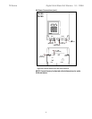
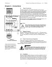
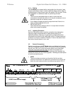
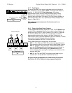
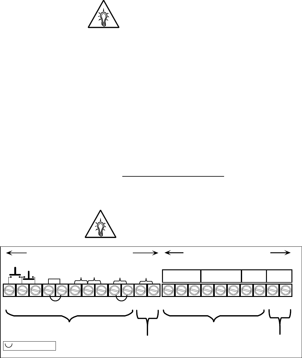
4.2 Control Connections
Control connections on the TE Series starter are divided into 2 groups.
With the unit oriented vertically, TB1 is a 12-point DC terminal block (on
the left), and TB2 is a 10 point AC terminal block (on the right side).
These are removable terminal blocks
for ease of connection and
servicing, and are provided with different spacing (pitch) between the
header pins so they are not interchangeable. Following are descriptions
of control connection points.
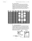
NOTE:
Terminal numbers are shown on the side of the first and last
terminal of each block. An additional 3 point terminal on the far left
side is for serial communication connections (see section 5.6.11).
N C
JOG
RAMP2
PTC
OPTO
24VDC from internal supply
240VAC max. from
customer source
TB1: 12 terminals, #1-12
TB2: 10 Terminals, #13-22
Opto-Isolated Triac Switch
10-250VAC/DC 50mA max.
1 2 3 ............................................... 11 12
13 14 ...........................19 20
1
NC NO. C
1
A1 A2
2
NC NO. C
3
NO. C
= Factory installed jumpers
120VAC Control Power
(or 240VAC if ordered)