


TE Series Digital Solid State Soft Starters 18 – 1250A
17
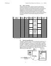
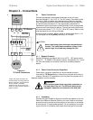
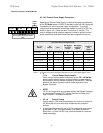
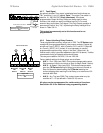
Figure 4.2: Control Terminal Blocks
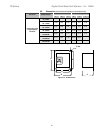
4.2.1 AC Control Power Supply Connection
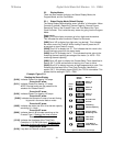
Separate AC Control Power supply is required to power the electronics
of the TE Series starter. 120VAC is standard, order 240 VAC (optional)
if necessary for your line power supply configuration. The control
voltage must be connected to terminals marked A1 and A2 of TB-2 as
shown in figure 4.2.1 (these are also Terminal #s 21 and 22). This
control voltage must be customer supplied, unless an optional control
power transformer (see table below) has been supplied with the unit.
4
.2.1.a Control Power Requirements
When sizing a control power transformer for the TE…-BP Series
starter use the above chart for minimum sizes or supply capacity.
Any additional control devices powered by the same CPT must be
added to the above figures to ensure proper operation of the
Bypass Contactor.
NOTE:
TE-210 and larger units are available without the Bypass Contactor,
but fans are still included. CPT can be sized for fan loads only if
used in NEMA 1 ventilated enclosures.
4.2.1.b Control Fusing
Output relays in TB2 must be protected from currents in excess of
5A, either with a fuse or with other suitable current protection
devices.
A dedicated fault output for use in PLC or interposing relay control
is available on TB1. This opto-isolated Triac switch is rated for
50mA max., 10-250V AC/DC. Any circuit connected to it must be
fused accordingly.
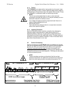
AC Control Power VA Requirements
TE …-BP
Model
PC
Boards
Fans
-BP: Bypass
Contactor
Inrush
-BP: Bypass
Contactor
Sealed
Recommended
minimum
CPT
Rating
TE-18 to 48 48 (inc. in PCB) 95 9 100
TE-62 to 112 48 (inc. in PCB) 220 17 250
TE-150 to 160
48 72 298 12.3 500
TE- 210 to 276*
48 100 380 11.6 500
TE-360 to 450*
48 150 571 14 750
TE-550 to 900*
48 200 600 3.3 750
TE-1006 to 1250* 48 200 1900 48 2000
Table 3: TE Series Control Power Requirements
NOTE: * - P versions (w/o bypass) still require PCB and fans, plus user supplied bypass (if any).
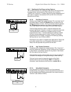
120VAC
Supply
Figure 4.2.1
Control Power Supply Connection
TB-2
1
NC NO. C
1
A1 A2
2
NC NO. C
3
NO. C