


TE Series Digital Solid State Soft Starters 18 – 1250A
84
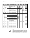
Appendix 5 (cont.) External OL Relay Applications
Across-the-Line (Direct-on-Line) Bypass
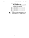
A suggested control schematic is shown below for using the TE …-BP
Series rated for Across-the-Line Bypass with an External Overload:
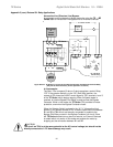
Figure APP5.2: TE Wiring for Across-the-Line Bypass Operation with External Overload Relay
(Only the terminals necessary for this operation are shown)
In this example:
The Start / Run command (2-wire or 3-wire) energizes a control Relay
“CR”. If the selector Switch is in the “SS” (Soft Start) position, the
contact of CR closes the 24VDC control signal to TB1, terminals 1 and 3
of the TE Series, which begins ramping. When At-Speed status is
reached, an internal Bypass Pilot Relay is used to close the Bypass
Contactor. While in this mode, the TE Series CPU provides full motor
protection, even when the Bypass Contactor closes.
When the Selector Switch is placed in the “A-T-L” (Across-the-Line)
position, a 2
nd
isolated contact of CR is used to close the circuit between
B1 and B2 of TB4 which are internally connected in parallel to the
Bypass Pilot Relay contact in the Bypass Contactor coil circuit. Since
the TE Series electronics may be out of service, an External Overload
is added which only works in this mode and protects the motor by
dropping out the connection between B1 and B2.
CAUTION
The circuit on TB-4 is at the same potential as the AC control voltage, but should not be
directly connected to it. PC board damage may result.
TE Starte
r
.
Bypass
Contacto
r
"BP"
Disconnect
o
r
Circuit
Breake
r
Solid Stat
e
.
Over Load.
MTR
G
R
/
L1
T
/
L3
S /
L2
U
/
T1
W
/
T3
V
/
T2
Externa
l
Over Loa
d
Of
f
S S
A
- T-L
1 2 3
A1 A2
A
C CONTROL POWER
Start / Run
Command
External
OL
TE...-BP Series
Internal Wiring
TE-TB-1
(24VDC)
TE-
TB-2
Bypass
Contacto
r
Coil
CR
CR
B1 B2
Internal Bypass
Pilot Rela
y
A
C
Control Powe
r
Potential
TE-
TB-4
BP
(2-wire or 3-wire)
97 98
CR