


TE Series Digital Solid State Soft Starters 18 – 1250A
21
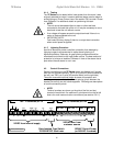
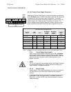
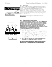
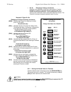
4.2.7 Fault Signal
An optically isolated Triac output is dedicated as a fault indicator on
TB1, terminals 11 and 12, labeled “Opto”. The output Triac switch is
rated for 10 - 250 VAC/DC, 50 mA (maximum). If the three
programmable Output Auxiliary Relays are being used for other
functions, this output can easily be hooked up to a PLC or small
external relay to provide a Fault signal. This Fault Output operation is
permanently fixed at “Any Trip”, duplicating the Relay setting #16 as
shown in Table 5.6.10.
This output is permanently set to this function and is not
programmable.
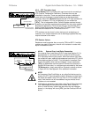
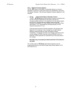
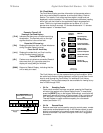
4.2.8 Output (Auxiliary) Relay Contacts
Three programmable auxiliary relays are on TB2. The TE Series starter
comes with three programmable dry relay output contacts. Outputs #1
and #2 are Form C (SPDT), with a Common, N.O. and N.C. Output #3
is a Form A, (SPST), N.O. contact. It is not necessary to use the
programmable output auxiliary relays in the Start / Stop circuit. An
internal seal-in relay is provided elsewhere (see 4.2.2.a above). Toshiba
recommends fusing all contacts with external fuses.
The relays are rated for 240 VAC, 5 A and 1200 VA.
Factory default settings for these relays are as follows:
AUX 1 – Run / Stop (see F060) This contact changes state upon a
Start command, returns to normal on Stop (or Begin Decel if active).
AUX 2 – At-Speed / Stop (see F061) This contact changes state
upon the TE Series detecting At-Speed, and returns to normal on
Stop. At-Speed is determined by the TE Series detecting the
current dropping after reaching End-of-Ramp, or a maximum of 30
seconds after Start.
AUX 3 – Any Trip (see F062) This contact closes when any trip
condition # 5 – 15 (as defined in Table 5.6.10) occurs.
All relays can be reprogrammed for a wide variety of functions.
See Section 5.6.10 for additional relay programming details.
N C
JOG
RAM P2
PTC
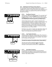
OPTO
Figure 4.2.7:
Fault Output Opto-Triac Connection
TB-1
11 12
External Fault Relay
or PLC Input
R
Control Power or PLC Source
K3
Internal Connections
Figure 4.2.8
Auxiliary Relay Connections
TB-2
AUX.
RELAY #1
AUX.
RELAY #3
AUX.
RELAY #2
13 14 15 16 17 18 19 20
1
NC NO. C
1
A1 A2
2
NC NO. C
3
NO. C
K5K4