ENGINE AND PERIPHERALS
Overhauling the engine
10
10-86
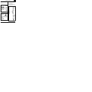
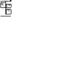
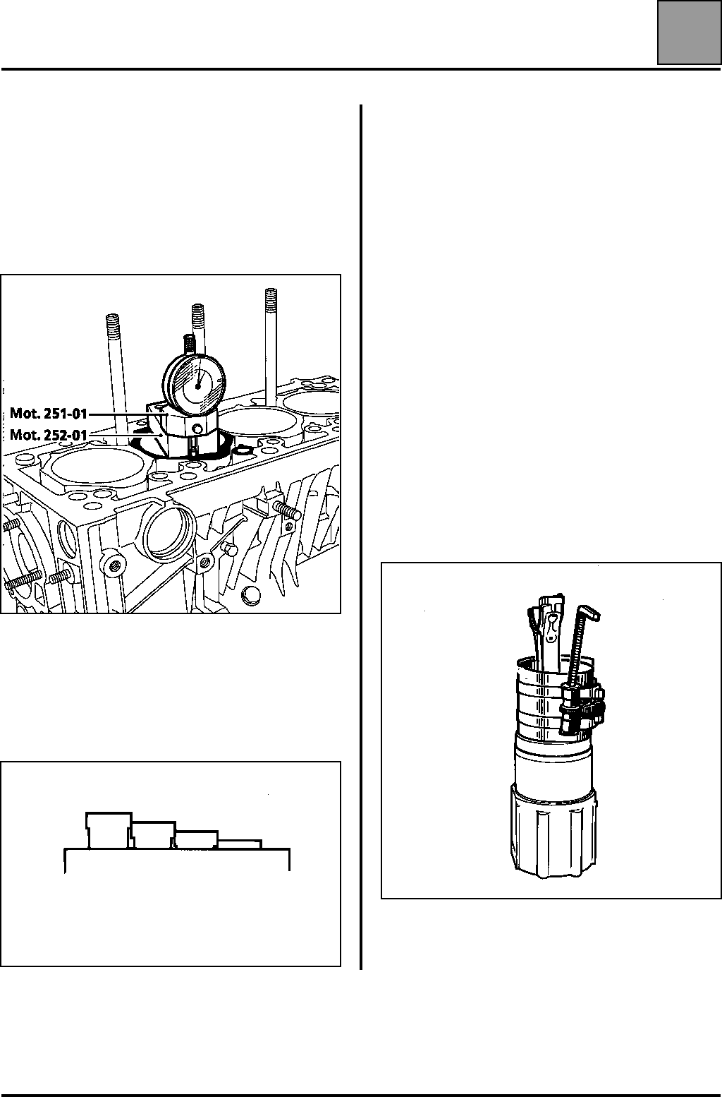
Therefore, the protrusion (X) should be checked in the
following way:
– place the cylinder liner not fitted with seals, in the
cylinder block,
– check protrusion (X) using tools Mot. 251-01 and
Mot. 252-01. It should be between 0.07 and
0.13 mm.
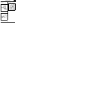
Position the cylinder liners so that:
– the protrusion is graduated from cylinder n˚ 1 to
cylinder n˚ 4 (or vice versa),
– the difference in protrusion between two
neighbouring cylinders is no more than 0.04 mm (in
tolerance).
NOTE: the parts supplied in the cylinder liner-piston
operation kit are identical to those used for this
operation. Mark the parts in each box from A to D to
ensure they remain identical.
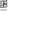
Once the correct protrusion has been obtained,
reassemble groups A, B, C and D with the cylinder
liners, pistons and gudgeon pins and mark their
position in the cylinder block.
NOTE: If the protrusion is incorrect, check using a new
cylinder liner set to find out whether the cylinder block
or the cylinder liner is at fault.
REFITTING CYLINDER LINERS - PISTONS - CON
RODS
Oil the pistons.
Fit the piston-con rod assemblies into the cylinder
liners with the tool, paying attention to the direction
(the V towards the flywheel).
The big end surfaces must be parallel with the flat
bottom of the cylinder liner.
16528R


