6G7 ENGINE (E-W) -
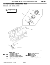
Piston and Connecting Rod
11A-12-5
"
B
A
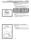
OIL RING
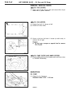
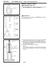
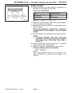
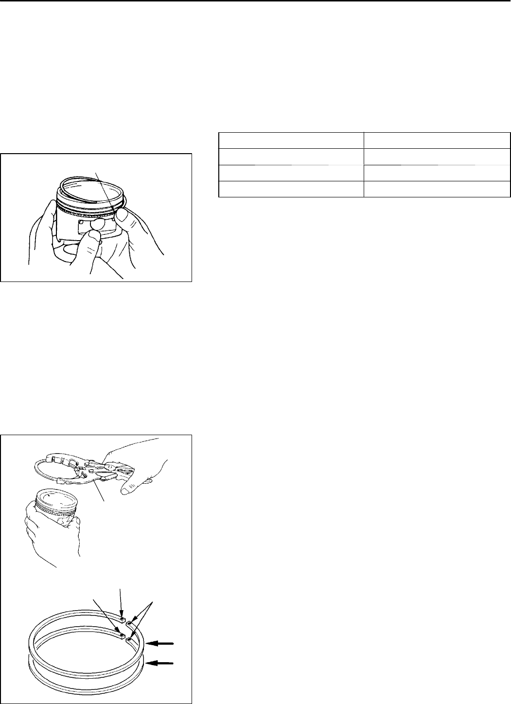
(1) Install the oil ring spacer into the piston ring groove. Next
install the upper side rail into the piston ring groove, and
then install the lower side rail.
NOTE
D There is no distinction between the upper and lower
surfaces of the side rail and spacer.
D The spacer and side rail (new part) are painted the
following colour to enable size identification.
Side rail Identification colour
S.T.D. None
0.50 mm O.S. Blue
1.00 mm O.S. Yellow
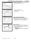
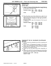
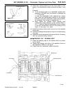
(2) The side rail can be inserted easily into the piston groove
by first inserting one end and then pushing the rail into
place while turning it by hand as shown.
Caution
D
The side rail may break if a ring expander is used.
(3) After installation into the piston, make sure the side rail
turns smoothly in either direction.
"
C
A
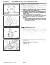
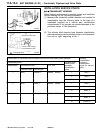
PISTON RING NO. 2 / PISTON RING NO. 1
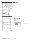
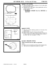
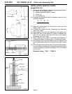
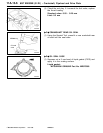
(1) Using piston ring expander, fit No. 2 and then No. 1 piston
ring into position.
NOTE
D Note the difference in shape between No. 1 and No.
2 piston rings.
D Install piston rings No. 1 and No. 2 with their side
having marks facing up (on the piston crown side).
PWEE9615
E
Dec. 1996Mitsubishi Motors Corporation
7EN0451
Side rail end
9EN0524
Piston ring expander
Size mark
Identification mark
7EN0452
Identification mark


