6G7 ENGINE (E-W) -
Timing Belt
11A-6-4
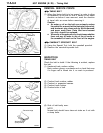
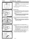
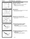
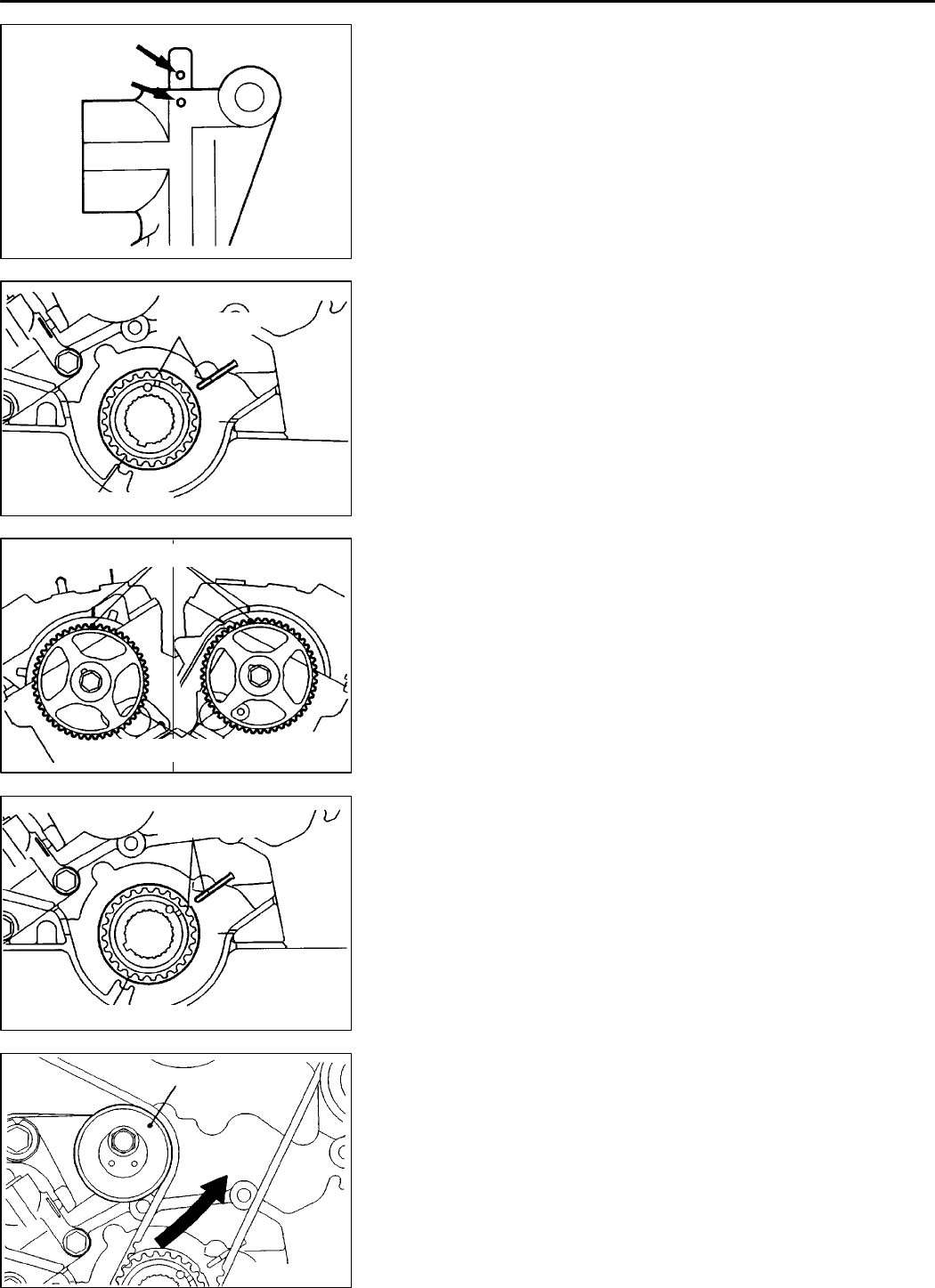
2 Slowly close the vice to force the rod in until the set
hole
(A)
of the rod is lined up with the set hole
(B)
of the cylinder.
3 Insert a metal wire (1.4 mm in diameter) into the set
holes.
4 Remove the auto-tensioner from the vice.
(2) Install the auto tensioner on the cylinder block through
the oil pump case.
"
C
A
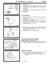
TIMING BELT
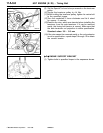
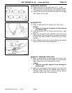
(1) Turn the crankshaft sprocket to position its timing mark
3 teeth away from the timing mark on the crankcase. (That
is, slightly lower the No. 1 piston from the top dead centre
on the compression stroke.)
Caution
D
If the camshaft sprocket is turned with the piston
at the top dead centre on the compression stroke,
valves may interfere with the piston.
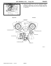
(2) Align the timing marks for the left bank camshaft sprocket.
(3) Align thetiming marks forthe right bank camshaftsprocket.
Caution
D
The camshaft sprocket may turn un-intentionally
due to the valve spring tension. Take care not
to injure your fingers.
(4) Align timing marks for the crankshaft sprocket.
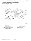
(5) Install the timing belt over the sprockets in the following
sequence.
1 Place the timing belt over the crankshaft. While
applying tension to the belt, set it over th e idler pulley.
2 Place the belt over the left bank camshaft sprocket.
3 While applying tension to the belt, place it over the
water pump pulley.
4 Place the belt over the right bank camshaft sprocket.
5 Place the belt over the tensioner pulley.
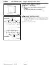
(6) While pressing the tensioner pulley lightly against the
timing belt, temporarily tighten its centre bolt.
(7) Check that all timing marks are in alignment.
PWEE9615
E
Dec. 1996Mitsubishi Motors Corporation
7EN0227
A
B
7EN0741
Timing mark
Crankshaft sprocket
7EN0742
Right bank Left bank
Crankshaft sprocket
Timing mark
7EN0740
Timing mark
Crankshaft sprocket
7EN0743
Tensioner pulley


