4G6 ENGINE (E-W) -
Piston and Connecting Rod
11A-11-7
"
G
A
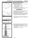
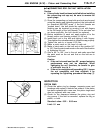
CONNECTING ROD CAP NUT INSTALLATION
Caution
D
If the cylinder head has been installed before installing
the connecting rod cap nut, be sure to remove the
spark plugs.
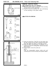
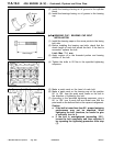
(1) Since the connecting rod cap bolts and nuts are torqued
using the plastic area tightening method, the bolts should
be examined BEFORE reuse. If the bolt threads are
“necked down”, the bolt should be replaced.
Necking can be checked by running a nut with fingers
to the full length of the bolt threads. If the nut does not
run down smoothly, the bolt should be replaced.
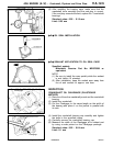
(2) Before installation of each nut, apply engine oil to the
thread portion and bearing surface of the nut.
(3) Install each nut to the bolt and tighten it with fingers.
Then tighten the nuts alternately to install the cap properly.
(4) Tighten the nuts to a torque of 20 Nm.
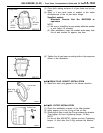
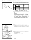
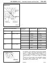
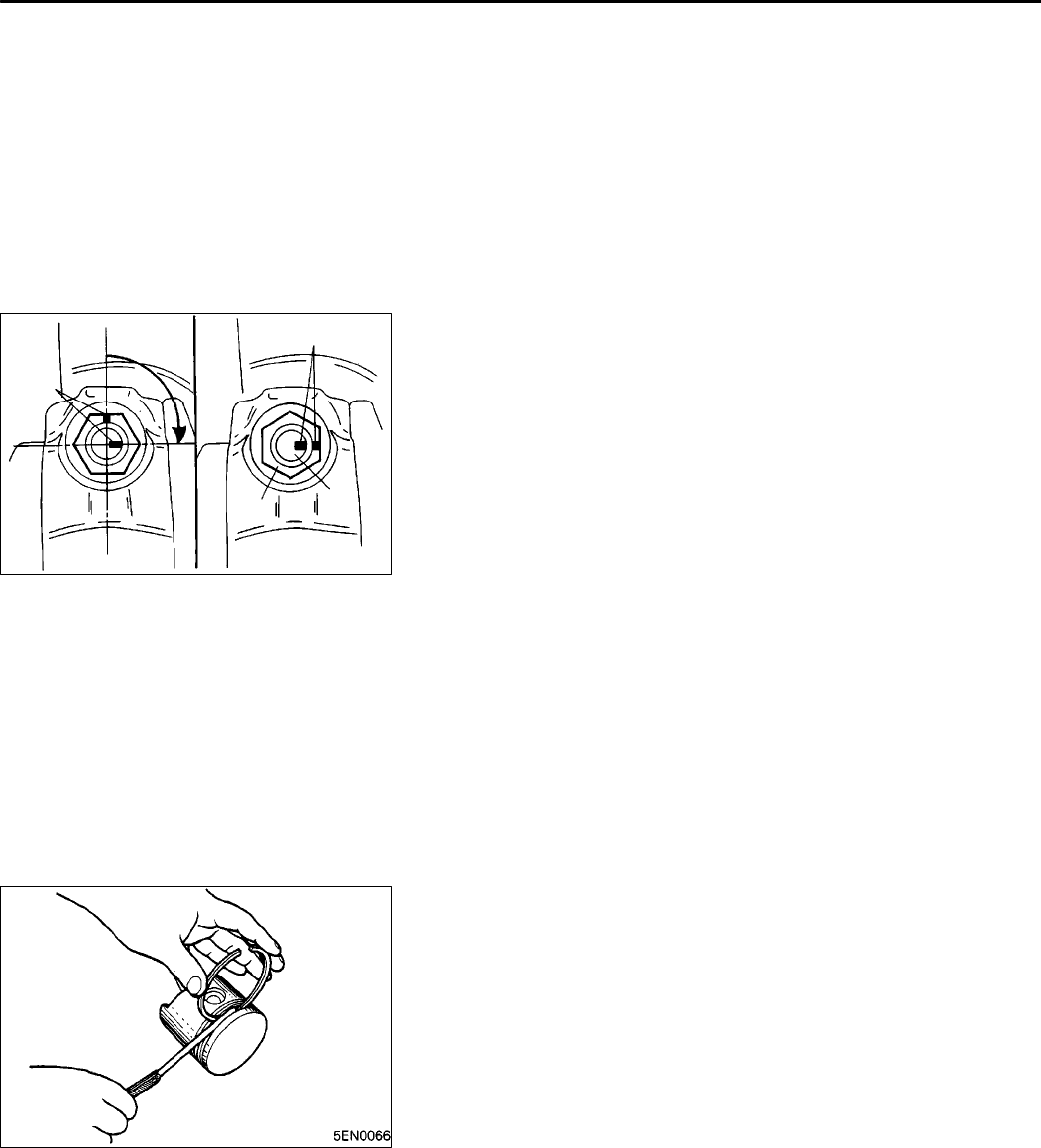
(5) Make a paint mark on the head of each nut.
(6) Make a paint mark on the bolt end at the position 90
_
to 100
_
from the paint mark made on the nut in the direction
of tightening the nut.
(7) Give a 90
_
to 100
_
turn to the nut and make sure that
the paint mark on the nut and that on the bolt are in
alignment.
Caution
D
If the nut is turned less than 90
_
, proper fastening
performance may not be expected. When
tightening the nut, therefore, be careful to give
a sufficient turn to it.
D
If the nut is overtightened (exceeding 100
_
), loosen
the nut completely and then retighten it by
repeating the tightening procedure from step (1).
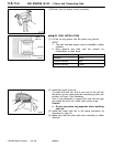
INSPECTION
PISTON RING
(1) Check the piston ring for damage, excessive wear, and
breakage and replace if defects are evident. If the piston
has been replaced with a new one, the piston rings must
also be replaced with new ones.
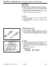
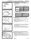
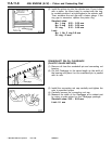
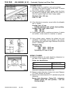
(2) Check for the clearance between the piston ring and
ring groove. If the limit is exceeded, replace the ring or
piston, or both.
Standard value: 0.02 - 0.06 mm
Limit: 0.1 mm
PWEE9616
E
Dec. 1996Mitsubishi Motors Corporation
6AE0298
90
_
- 100
_
Paint mark
Paint
mark
Nut
Bolt


