


4G6 ENGINE (E-W) -
Fuel Part (GDI)
11A-5a-5
"
F
A
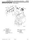
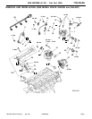
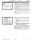
FUEL PUMP / FUEL FEED PIPE INSTALLATION
(1) Insert the fuel pump into the mounting hole in the pump
camshaft case, and secure it temporarily with 4 bolts
(tighten somewhat with a larger torque than finger tight).
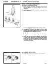
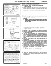
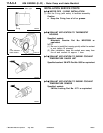
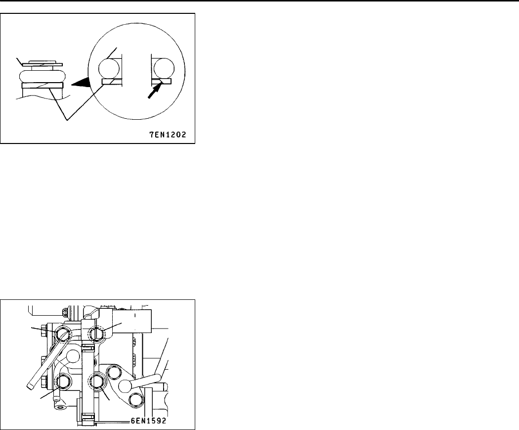
(2) Fit the backup rings and the O-ring on both ends of the
feed pipe. Note that the larger backup ring must be
installed with the inside cut surface in the direction shown
in the illustration.
(3) Lubricate the O-rings on both ends of the pipe with spindle
oil or gasoline.
(4) Insert the fuel feed pipe ends straight in the respective
mounting holes of the fuel and the delivery pipe. Be sure
to insert the pipe fully to the stop using care not to twist
it.
(5) Tighten the bolts at ends of the pipe to the specified
torque.
(6) Tighten the mounting bolts of the fuel pressure regulator
to the specified torque.
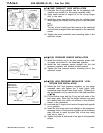
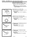
(7) Using a torque wrench having the minimum scale of 0.5
Nm, tighten the fuel pump mounting bolts in the following
order.
1) Tighten the bolts to 4.9 Nm in the order given in
the illustration.
2) Tighten the bolts to 17 Nm in the order given in the
illustration. The torque variation among 4 bolts must
be within 2 Nm.
Caution
D
Strictly observe the specified tightening torque.
Deviation from the specification can cause
problems such as leakage or the like.
(8) Clamp the fuel return pipe and feed pipe using the fuel
pipe bracket and clamp A, and tighten them lightly.
(9) Secure the fuel pipe bracket to the cam cap temporarily.
(10)Tighten the bolts which are securing the pipes temporarily
to the specified torque.
(11)Tighten the bolts on the beam cam shaft side which have
been temporarily tightened to the specified torque.
AddedPWEE9616-A
E
Aug. 1998Mitsubishi Motors Corporation
Backup ring
(Mountable in
either direction)
O-ring
Backup ring
Cut surface
3
1
2
4