


4G6 ENGINE (E-W) -
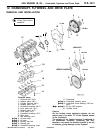
Crankshaft, Flywheel and Drive Plate
11A-12-2
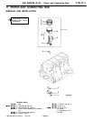
REMOVAL SERVICE POINT
A
A
"
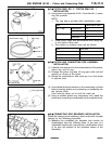
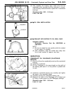
OIL JET REMOVAL
(1) Knock out the oil jets using an appropriate metal rod.
Caution
D
Be careful not to scratch the cylinder wall.
D
Do not reuse the removed oil jets.
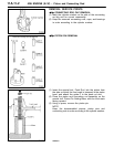
INSTALLATION SERVICE POINTS
"
A
A
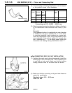
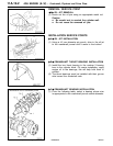
OIL JET INSTALLATION
(1) Using a 4.5 mm diameter pin punch, drive in the oil jet
to the crankshaft journal until it seats to the bottom.
"
B
A
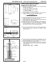
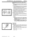
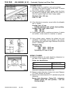
CRANKSHAFT THRUST BEARING INSTALLATION
(1) Install the two thrust bearing in the number 3 bearing
bore in the cylinder block. For easier installation, apply
engine oil to the bearings; this will help hold them in
position.
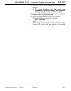
(2) The thrust bearings must be installed with their groove
side toward the crankshaft web.
"
C
A
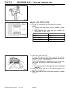
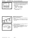
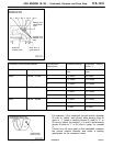
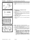
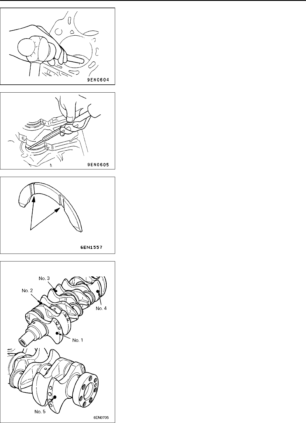
CRANKSHAFT BEARING INSTALLATION
(1) From the following table, select a bearing whose size
is appropriate for the crankshaft journal outside diameter.
RevisedPWEE9616-A
E
Aug. 1998Mitsubishi Motors Corporation
Groove
Identification color of crankshaft journal