4G6 ENGINE (E-W) -
Fuel Part (GDI)
11A-5a-4
"
C
A
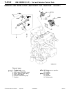
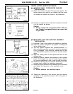
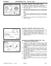
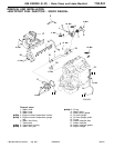
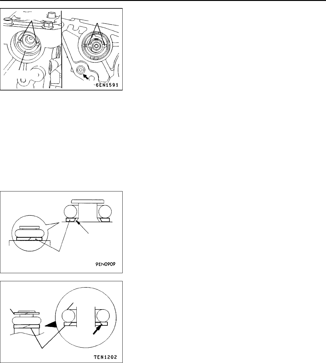
PUMP CAMSHAFT CASE INSTALLATION
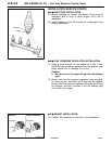
(1) Lubricate the O-ring (smaller one for oil passage) with
vaseline and install it in the pump camshaft case.
(2) Apply small amount of engine oil to the O-ring (larger
one) in the case.
(3) Install the pump camshaft case onto the cylinder head
while aligning its coupling with the groove in the camshaft
end.
NOTE
The key of the coupling and the groove in the camshaft
end are both arranged offset with respect to the camshaft
center.
(4) Tighten the pump camshaft case mounting bolts to the
specified torque.
"
D
A
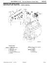
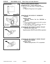
FUEL PRESSURE SENSOR INSTALLATION
(1) Install the backup ring to the fuel pressure sensor with
its inside cut surface in the illustrated direction.
(2) Install the fuel pressure sensor straight into the fuel
pressure regulator with labeled surface upward.
(3) Tighten the fuel pressure sensor mounting bolt to the
specified torque.
"
E
A
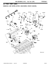
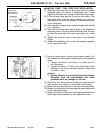
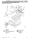
FUEL HIGH PRESSURE REGULATOR / FUEL
RETURN PIPE INSTALLATION
(1) Install the fuel high pressure regulator on the pump
camshaft case and tighten the 3 bolts lightly (with
somewhat larger torque than finger tight). Tightening to
the specification is to be carried out in the step described
in "
F
A.
(2) Fit the backup rings and the O-ring on both ends of the
fuel return pipe. Note that the larger backup ring must
be installed with the inside cut surface in the direction
shown in the illustration.
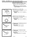
(3) Lubricate the O-rings on both ends of the pipe with spindle
oil or gasoline.
(4) Insert the fuel return pipe ends straight in the respective
mounting holes of the pressure regulator and the delivery
pipe. Be sure to insert the pipe fully to the stop using
care not to twist it.
(5) Tighten the bolts at both ends of the pipe to the specified
torque.
AddedPWEE9616-A
E
Aug. 1998Mitsubishi Motors Corporation
Grooved
Coupling
Camshaft
O-ring
Backup ring
Cut surface
Backup ring
(Mountable in
eitherdirection)
O-ring
Backup ring
Cut surface


