


4G6 ENGINE (E-W) -
Piston and Connecting Rod
11A-11-3
INSTALLATION SERVICE POINTS
"
A
A
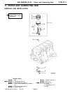
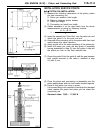
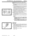
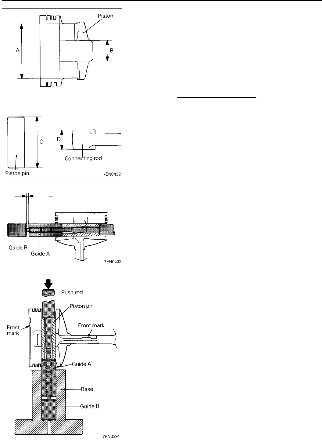
PISTON PIN INSTALLATION
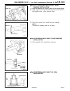
(1) Measure the following dimensions of the piston, piston
pin and connecting rod.
A: Piston pin insertion hole length
B: Distance between piston bosses
C: Piston pin length
D: Connecting rod small end width
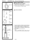
(2) Obtain dimension L (to be used later) from the above
measurements by using by following formula.
L=
(A - C) - (B - D)
2
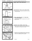
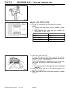
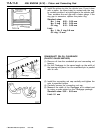
(3) Insert the special tool, Push Rod, into the piston pin and
attach the guide A to the push rod end.
(4) Assemble the connecting rod in the piston with their front
marks facing the same direction.
(5) Apply engine oil to the entire periphery of the piston pin.
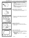
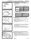
(6) Insert the piston pin, push rod and guide A assembly
having assembled in step (3) from the guide A side into
the piston pin hole on the front marked side.
(7) Screw the guide B into the guide A until the gap between
both guides amounts to the value L obtained in step
(2) plus 3 mm.
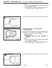
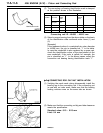
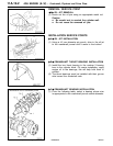
(8) Place the piston and connecting rod assembly onto the
piston setting base with the front marks directed upward.
(9) Press-fit the piston pin using a press.
If the press-fitting force required is less than the standard
value, replace the piston and piston pin set or/and the
connecting rod.
Standard value: 7,350 - 17,200 N
PWEE9616
E
Dec. 1996Mitsubishi Motors Corporation
3mm+L