


4G6 ENGINE (E-W) -
Crankshaft, Flywheel and Drive Plate
11A-12-1
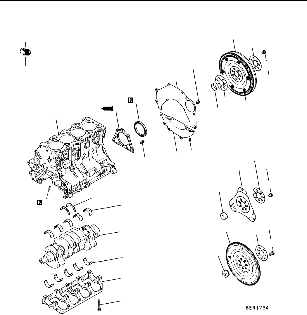
12. CRANKSHAFT, FLYWHEEL AND DRIVE PLATE
REMOVAL AND INSTALLATION
1
2
3
4
5
10
11
13
14
15
16
17
18
12
21
A
11 Nm
132 Nm
9Nm
132 Nm
6
7
8
9
11 Nm
Apply engine oil to all
moving parts before
installation.
<GALANT>
<SPACE WAGON>
7
132 Nm
6
8
9
20
19
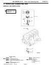
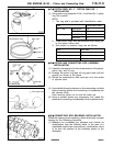
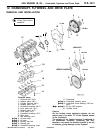
Removal steps
1. Flywheel bolt <M/T>
2. Adapter plate <M/T>
3. Flexible flywheel <M/T>
4. Adapter plate <M/T>
5. Crankshaft bushing <M/T>
6. Drive plate bolt <A/T>
7. Adapter plate <A/T>
8. Drive plate <A/T>
9. Crankshaft bushing <A/T>
10. Rear plate
11. Bell housing cover
"FA 12. Oil seal case
"EA 13. Oil seal
"DA 14. Bearing cap bolt
"DA 15. Bearing cap
"CA 16. Crankshaft bearing, lower
17. Crankshaft
"CA 18. Crankshaft bearing, upper
"BA 19. Crankshaft thrust bearing <GDI en-
gine>
AA""AA 20. Oil jet <GDI engine>
21. Cylinder block
Caution
On the flexible wheel equipped engines, do not
remove any of the bolts “A” of the flywheel shown
in the illustration.
The balance of the flexible flywheel is adjusted in
an assembled condition. Removing the bolt,
therefore, can cause the flexible flywheel to be out
of balance, giving damage to the flywheel.
RevisedPWEE9616-A
E
Aug. 1998Mitsubishi Motors Corporation