


4G6 ENGINE (E-W) -
Piston and Connecting Rod
11A-11-5
"
C
A
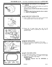
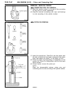
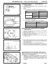
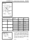
PISTON RING NO. 2 / PISTON RING NO. 1
INSTALLATION
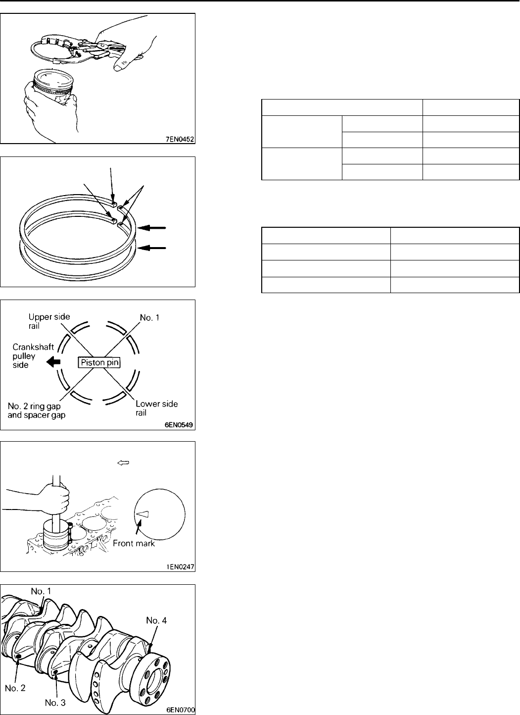
(1) Using piston ring expander, fit No. 2 and then No. 1 piston
ring into position.
NOTE
1. The ring end is provided with identification mark.
Item Identification mark
No. 1 ring 4G63 SOHC 1R
4G64 GDI T
No. 2 ring 4G63 SOHC 2R
4G64 GDI 2T
2. Install piston rings with identification mark facing up,
to the piston crown side.
3. Size marks on position rings are as follows.
Size Size mark
Standard None
0.50 mm oversize 50
1.00 mm oversize 100
"
D
A
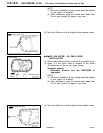
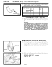
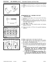
PISTON AND CONNECTING ROD ASSEMBLY
INSTALLATION
(1) Liberally coat engine oil on the circumference of the piston,
piston ring, and oil ring.
(2) Arrange the piston ring and oil ring gaps (side rail and
spacer) as shown in the figure.
(3) Rotate the crankshaft so that crank pin is on the center
of cylinder bore.
(4) Use suitable thread protectors on the connecting rod bolts
before inserting piston and connecting rod assembly into
the cylinder block.
Care must be taken not to nick the crank pin.
(5) Using a suitable piston ring compressor tool, install the
piston and connecting rod assembly into the cylinder block.
"
E
A
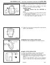
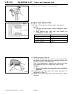
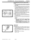
CONNECTING ROD BEARINGS INSTALLATION
When the bearing needs replacing, select and install a proper
bearing by the following procedure.
(1) Measure the crankshaft pin diameter and confirm its
classification from the following table. In the case of a
crankshaft supplied as a service part, identification colors
of its pins are painted at the positions shown in the
illustration.
RevisedPWEE9616-A
E
Aug. 1998Mitsubishi Motors Corporation
9EN0524
Identification mark
Identification mark
Side mark
No. 1
No. 2
Timing belt side
RevisedPWEE9616-A
E
Aug. 1998Mitsubishi Motors Corporation