


4G6 ENGINE (E-W) -
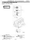
Piston and Connecting Rod
11A-11-6
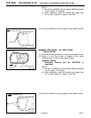
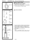
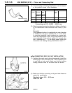
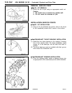
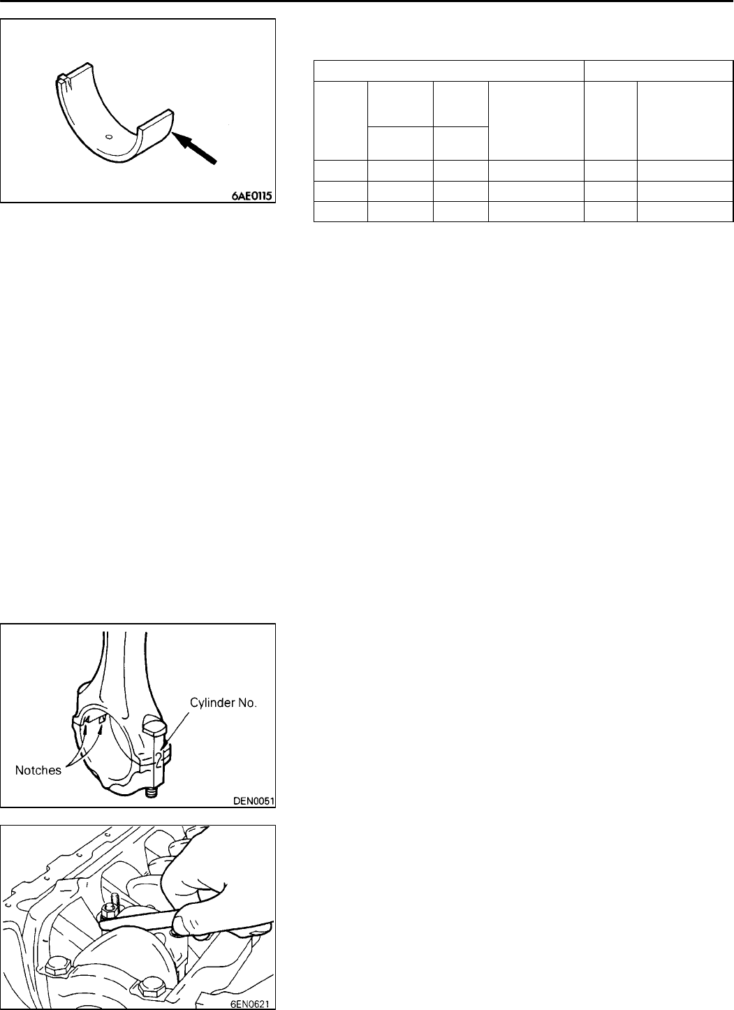
(2) The connecting rod bearing identification mark is stamped
at the position shown in the illustration.
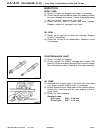
Crankshaft pin Connecting rod bearing
Classi-
fication
Identifica-
tion mark
Identifi-
cation
color
O. D. mm Identi-
fication
mark
Thickness mm
Produc-
tion part
Service
part
1 None Yellow 44.995- 45.000 1 1.478 - 1.491
2 None None 44.985 - 44.995 2 1.491 - 1.495
3 None White 44.980 - 44.985 3 1.495 - 1.499
Connecting rod I.D.: 48.000 - 48.015 mm
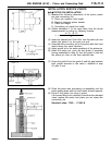
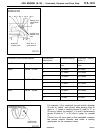
(3) Select a proper bearing from the above table on the basic
of the identification data confirmed under items (1) and
(2).
[Example]
If the measured value of a crankshaft pin outer diameter
is 44.996 mm, the pin is classified as “1” in the table.
In case the crankshaft is also replaced by a spare part,
check the identification colors of the pins painted on the
new crankshaft. If the color is yellow, for example, the
pin is classified as “1”. In the above cases, select the
connection rod bearing having identification mark “1”.
"
F
A
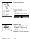
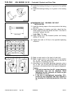
CONNECTING ROD CAP NUT INSTALLATION
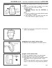
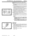
(1) Verifying the mark made during disassembly, install the
bearing cap to the connecting rod. If the connecting rod
is new with no index mark, make sure that the bearing
locking notches come on the same side as shown.
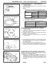
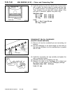
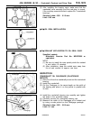
(2) Make sure that the connecting rod big end side clearance
meets the specification.
Standard value: 0.10 - 0.25 mm
Limit: 0.4 mm
PWEE9616
E
Dec. 1996Mitsubishi Motors Corporation
Identification mark