


6
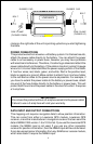
Lowrance Accessory Wiring Diagrams
Since there are many different combinations of accessories that are used
with the GlobalMap 2000, the drawings on the next four pages can help
with the installation. (Note: The black connector on the GlobalMap 2000 is
covered by a black plastic cap. Carefully pry this cap off to gain access to
the connector.)
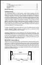
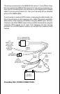
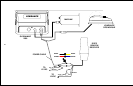
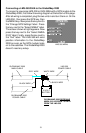
The diagram on page 7 shows the GlobalMap 2000 connected to a
Lowrance GPS receiver and DGPS receiver, and both 192 kHz and 50 kHz
(SAM) sonar modules. In order to use both a DGPS receiver and a SAM
module, (or two SAM modules) you must use the optional DGPS Dual
Frequency Interface. When this adapter is used, power to all Lowrance
accessories is switched through the GlobalMap 2000, so accessory
switches aren’t necessary. Any other manufacturer’s accessory will need
to be connected directly to 12-volt power, through it’s own fuse.
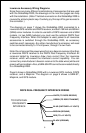
Note: Do not connect the power wires from any beacon receiver other than
a Lowrance DGPS receiver to the DGPS Dual Frequency Interface! All
receivers tested by Lowrance draw more current than the Lowrance
receiver, which will exceed the interface’s current capability. You can
connect any manufacturer’s beacon receiver to the data wires (white and
green) without problem. Also, a SAM-50HPD cannot be connected directly
to a GlobalMap 2000.
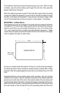
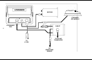
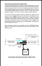
Page 8 shows a GlobalMap 2000 with a Lowrance GPS module, DGPS
receiver, and a MapLink. The diagram on page 9 shows a SAM-ST,
MapLink, and GPS module.
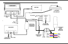
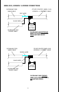
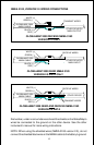
WHITE (TO DGPS RECEIVE)
GREEN (TO DGPS TRANSMIT)
BLUE (SWITCHED +12 VOLTS)
BROWN (GROUND)
RED (TO +12 VOLTS)
BLACK (GROUND)
TO DGPS DUAL
FREQUENCY
INTERFACE
DGPS DUAL FREQUENCY INTERFACE WIRING