


1
XJ Series 2001
DATE OF ISSUE: September 2000
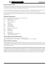
Electrical Guide Format
This Electrical Guide is made up of two major sections. The first section, at the front of the book, provides general information
for and about the use of the book, and information and illustrations to aid in the understanding of the XJ Series electrical / elec-
tronic systems, as well as the location and identification of components.
The second section includes the Figures, which are the basis of the book. Each Figure is identified by a Figure Number
(i.e. Fig. 01.1) and Title, and is accompanied by a page of data containing information specific to that Figure.
It is recommended that the user read through the front section of the book to develop a familiarity with the layout of the
book and with the system of symbols and abbreviations used. The Table of Contents on the following pages should help
to guide the user.
Standard Abbreviations
The following abbreviations are used throughout this Electrical Guide:
ACP Audio Control Protocol Network
B+ Battery Voltage
CAN Controller Area Network
DI Direction Indicator
LH Left-Hand
LHD Left-Hand Drive
LWB Long Wheelbase
N/A Normally Aspirated
NAS North American Specification
RH Right-Hand
RHD Right-Hand Drive
ROW Rest of World
SC Supercharged
SCP Standard Corporate Protocol Network
VIN Vehicle Identification Number
Vehicle Identification Numbers (VIN)
VIN ranges are presented throughout the book in the following manner:
➞
VIN 123456 indicates “up to VIN 123456”; VIN 123456
➞
indicates “from VIN 123456 on”.
XJ Series Electrical System
The vehicle electrical system is a ground side switched system. The ignition switch switches ground circuits on / off to
complete system circuits and apply power. Circuits that require ignition switch position control are supplied with “ignition
switched grounds”. Both power grounds (high current consumers) and logic grounds (electronic switching circuits) are
used throughout the system.
Three data networks are employed in the vehicle: a high speed Controller Area Network (CAN) for the engine, drive train
and related systems, a Standard Corporate Protocol network (SCP) for the body systems, and an Audio Control Protocol
network (ACP) for certain In-Car Entertainment and Telephone functions. Any vehicle subsystem depicted on the figures
with the CAN or SCP included uses data derived from the network, or transmits data via the network to achieve control.
Messages for both networks are cataloged in the Appendix of this book. In addition to the two networks, the vehicle uses
a serial data bus (ISO) for diagnostics, security sounder operation and for the programming of certain control modules.
Introduction