


Refer to the front of this book for detailed information and illustrations regarding the location and identification of harnesses, relays, grounds, control
modules and control module pins.
DATE OF ISSUE: September 2000
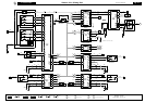
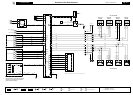
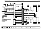
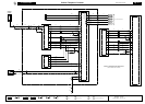
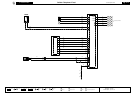
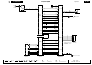
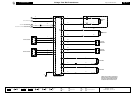
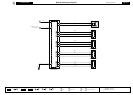
Fig. 17.2
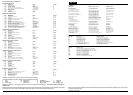
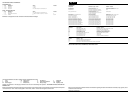
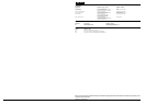
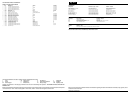
COMPONENTS
Component Connector / Type / Color Location / Access
CELLULAR PHONE CONTROL MODULE (FIXED PHONE) IC25 / TELEPHONE / PROPRIETARY RH TRUNK
TELEPHONE ANTENNA RT6 / COAXIAL CONNECTOR BELOW CENTER CONSOLE GLOVE BOX
RT7 / COAXIAL CONNECTOR HEATED BACKLIGHT / HEADLINING / REAR
TELEPHONE HANDSET – FRONT RT3 / TELEPHONE / PROPRIETARY CENTER CONSOLE
TELEPHONE MICROPHONE CA67 / 2-WAY MULTILOCK 040 / BLUE ROOF CONSOLE
HARNESS-TO-HARNESS CONNECTORS
Connector Type / Color Location / Access
RT2 10-WAY MULTILOCK 070 / WHITE BELOW CENTER CONSOLE GLOVE BOX
GROUNDS
Ground Location / Type
CA38R EYELET (PAIR) – LH HEELBOARD POST GROUND SCREW