


158 GPSMAP 496 Owner’s Manual
Appendix > Installation Information
Installation Information
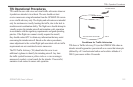
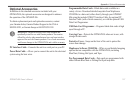
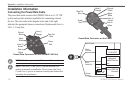
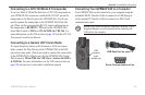
Connecting the Power/Data Cable
The power/data cable connects the GPSMAP 496 to an 11–35 VDC
system and provides interface capabilities for connecting external
devices. The color code in the diagram below and to the right
indicates the appropriate harness connections. Replacement fuse is a
3AG - 1.5 Amp fuse.
Power/Data Connector on the GPSMAP 496 Unit
Data Out
Blue
Ground
Black
Voice (-)
Orange
Alarm
White
Power
Red
Voice (+)
Brown
Data In
Yellow
NOTE: The Alarm pin is used in Marine installations only.
NOTE: The Voice (+) and Voice (-) pins are intended for a
speaker in automotive installations. Do not connect the Voice
(+) and Voice (-) pins to an intercom or audio panel without rst
consulting the manufacturer.
Power/Data Connector on the Cable
Data Out
Blue
Ground
Black
Voice (-)
Orange
Alarm
White
Power
Red
Voice (+)
Brown
Data In
Yellow
Yellow:
Data In
Black:
Ground
Red: Power
11–35 VDC
(-) (+)
Autopilot/
NMEA Device
RXD +
RXD -
GSD 20
Sounder
(-)
(+)
White/Brown
White/Blue
Blue:
Data Out
Orange
Closed - On,
Open - Off
Switch