


55
Wiring and Interfacing
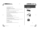
The StreetPilot III can be connected to a PC, beacon receiver, marine autopilot or other compatible
device using the supplied PC Interface Cable with RS-232 Serial Port Connector.
The StreetPilot III can be connected to a vehicle’s electrical system and a PC, beacon receiver,
marine autopilot, or other compatible device using the optional PC Interface Cable with Cigarette
Lighter Adapter.
The StreetPilot may be hard-wired to the vehicle’s electrical system (10-32 VDC) and a PC, beacon
receiver, marine autopilot or other compatible device using the Power/Data Cable with bare wire leads.
WARNING: the terms of the Garmin Warranty require that the Power/Data Cable with
bare wire leads be installed by experienced installers at a qualifi ed installation facility
(i.e., auto electrical accessory installation center). The user should not attempt installation
without proper knowledge of automotive electrical systems and skill in the use of special
tools or hardware required for installation.
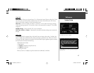
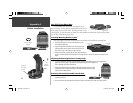
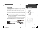
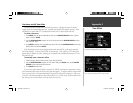
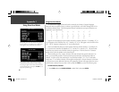
Consult the wiring diagrams at the side and bottom of the page for proper connections. (The male
connector on the back of the StreetPilot III and wiring leads are illustrated to the right, wiring lead
color coding is illustrated below.)
,
Appendix B
Wiring and Interfacing
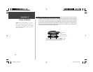
(-) Ground
Data OutData In
(+) Power
Power and Data Connections from the back of the unit.
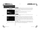
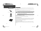
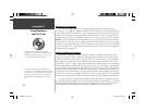
To remove the attached antenna for connection to a
remote antenna: rotate to the position shown in the
picture above and gently pull away from the unit.
The antenna port accepts a standard BNC connector.
190-00256-10_0B.indd 55 1/13/2003, 10:34:20 AM