


9-2
Grounding
The display unit contains a CPU. While it is
operating, it radiates noise, which can inter-
fere with radio equipment. Ground the unit
as follows to prevent interference:
• The ground wire should be 1.25sq or
larger.
• The ground wire should be as short as
possible.
• The signal ground and frame ground are
separated, however the power line is not
isolated. Therefore, do not connect the
signal ground to the frame ground when
connecting other equipment to a positive
ground battery.
• The antenna unit GPA-018 must be
grounded. Connect a ground wire of
1.25sq or larger (local supply) between
the ground terminal on the antenna unit
and a stainless steel screw fastened to the
mast. Coat the ground terminal, stainless
steel screw and crimp-on lugs on the
ground wire with silicone sealant.
• The power of the GP-35 is not isolated,
thus the earth lamp may light when the
antenna unit is grounded. If it lights, at-
tach two capacitors (1µF, 0.1µF) in par-
allel to the antenna earth line.
External equipment
The power supply port is commonly used
for connection of external equipment such
as navigation equipment or a PC. Refer to
the interconnection diagram on page S-1 for
connection.
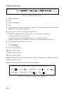
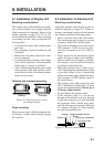
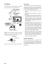
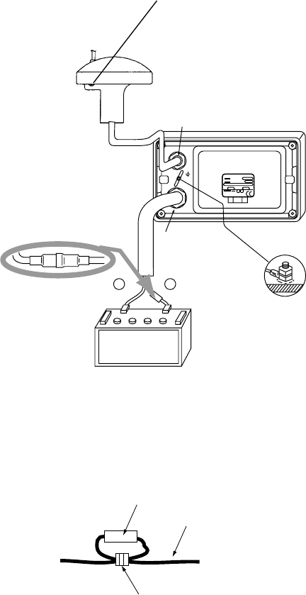
9.3 Wiring
The figure below shows where to connect
cables on the rear of the display unit.
{
|
Black
Red
POWER
(10.8-31.2 VDC)
Ground
1A FUSE
(+ Line)
ANTENNA UNIT
(For GP-35)
GPS ANT
DISPLAY
UNIT
Ground terminal
(Run ground wire
between it and
mast.)
Figure 9-3 Wiring
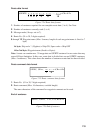
Note: The fuse holder contains a spring
which fixes the fuse. To fix the spring, tie
the line as shown in Figure 9-4.
Fuse holder
+ line (red)
Tie here.
Figure 9-4 How to fix spring in fuse holder