


9-1
9.1 Installation of Display Unit
Mounting considerations
The display unit can be installed on a table-
top, on the overhead, or in a panel (optional
flush mounting kit required). Refer to the
outline drawing on page D-2, D-3 or D-4
for installation instructions. When selecting
a mounting location, keep in mind the fol-
lowing points:
• Locate the unit away from exhaust pipes
and vents.
• The mounting location should be well
ventilated.
• Mount the unit where shock and vibra-
tion are minimal.
• Locate the display unit away from equip-
ment which generates electromagnetic
fields such as a motor or generator.
• Allow sufficient maintenance space at the
sides and rear of the unit and leave suffi-
cient slack in cables, to facilitate mainte-
nance and servicing.
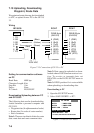
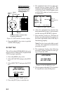
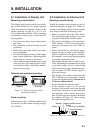
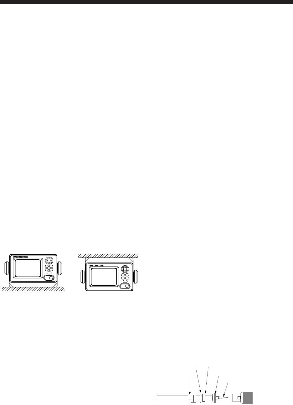
Tabletop and overhead mounting
Tabletop
Overhead
Figure 9-1 Tabletop and overhead
mounting methods
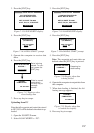
Flush mounting
There are two types of flush mounting kits.
For details, see the outline drawing on page
D-3 and D-4.
9. INSTALLATION
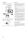
9.2 Installation of Antenna Unit
Mounting considerations
Install the antenna unit referring to the in-
stallation diagram on page D-1. When se-
lecting a mounting location for the antenna
unit, keep in mind the following points:
• Select a location out of the radar beam.
The radar beam will obstruct or prevent
reception of the GPS satellite signal.
• The location should be well away from a
VHF antenna. A GPS receiver is inter-
fered by a harmonic wave of a VHF an-
tenna.
• There should be no interfering object
within the line-of-sight to the satellites.
Objects within line-of-sight to a satellite,
for example, a mast, may block reception
or prolong acquisition time.
• Mount the antenna unit as high as pos-
sible. Mounting the antenna unit as high
as possible keeps it free of interfering
objects and water spray, which can inter-
rupt reception of GPS satellite signal if
the water freezes.
• The length of the whip antenna for the
GP-35 should be no longer than 1.2 meter
to prevent antenna damage. Do not use a
2.5 meter whip antenna.
• Do not shorten the antenna cable.
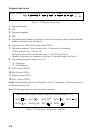
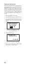
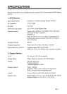
• If the antenna cable is to be passed
through a hole which is not large enough
to pass the connector, you may unfasten
the connector with a needle nose pliers
and 3/8-inch open-end wrench. Refasten
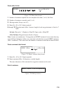
it as shown in Figure 9-2 after running
the cable through the hole.
Center pin (soldered)
Clamp nut
Connector shell
Gasket (reddish brown)
Washer
Shield
Figure 9-2 How to assemble the connector