


E-SERIES (May, 2004)44
E-SERIES (May, 2004) 45
STATEMENTS OF CONFORMITY
• The body installed by a subsequent stage manufacturer
and the Ford installed fuel system components are
located and mounted as follows:
– The body is mounted securely and is so designed
that when the completed vehicle is tested in any
manner specified by applicable provisions of
Standard 301,
(a) body components do not contact any fuel
system component at any time (other than at
the points where the fuel system is permanently
attached to the body), and,
(b) body deformation or movement relative to
the frame does not cause any fuel system
component to be penetrated, disconnected, or
otherwise damaged.
• The rear end of the body (excluding the rear bumper)
installed by a subsequent stage manufacturer does
not extend beyond (overhang) the rear edge of the
vehicle frame or frame extension. Any extension of the
vehicle frame must be constructed and attached so
as to perform as a continuation of the vehicle frame
when the completed vehicle is tested in any manner
specied by applicable provisions of Standard 301.
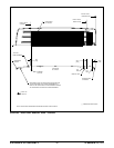
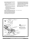
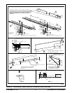
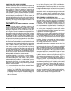
• The E-Series Basic (Stripped) Chassis aft-of-axle fuel
ller cap, pipe, hose(s), and attaching hardware are
installed as shown in Figure I, below. All components
must be securely retained to remain intact when the
completed vehicle is tested in any manner specied
by applicable provisions of Standard 301.
The Basic (Stripped) Chassis is equipped with a Fuel
Shutoff Switch. The switch is located on the column
support structure for E-Series and must not be relocated,
altered, or modied in any way.
301 (Continued on Page 45)
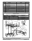
FIGURE I – E-SERIES CUTAWAY AND BASIC (STRIPPED) CHASSIS FUEL FILLER PIPE INSTALLATION
TO BACK OF
CUTAWAY CAB
OUTBOARD
SURFACE
OF
FRAME RAIL
FRONT OF
VEHICLE
E-SERIES E-350/450 CUTAWAY AND BASIC (STRIPPED)
CHASSIS AFT-OF-AXLE FUEL FILLER SYSTEM
C
OF FILLER NECK
C
L
TO L OF REAR
AXLE FO
R
STRIPPED CHASSIS
ALL W.B
.
601.4 12.7
[23.7 0.5]
+
+
FUEL TANK
319.
0
*
[12.56]
TOP OF
FILLER
PIPE
SUPPOR
T
40.2
[1.583
]
ROUTE FILL AND VENT
HOSE SO NO LO
W
SPOTS OCCUR
FUEL TANK
F
ILL PIPE
EXISTING 9.7 DIA. HOLE
S
(USED FOR EXHAUS
T
ON R.H. SIDE
)
N611645-S36
M10 SELF-TAPPING SCRE
W
(ATTACH TO SOUND
METAL ON FRAME)
N611131-S36
M4 SELF-TAPPING
SCREW
SECURE WITH TI
E
STRAPS AS REQUIRED
TO VENT HOSE
9A09
9
GROUND STRA
P
FUEL TANK
SCREW 3 REQíD
.
TORQUE TO 2.1- 2.9
Nm
18 - 26 IN.-LB.
2641.6 [104.0] [+0.00-2.00] [138 wb]
3149.6 [124.0] [+0.00-2.00] [158 wb]
3606.8 [142.0] [+0.00-2.00] [178 wb]
733.4
[28.875]
(MAX.)
CRITICAL CONTROL ITEM
NOTES:
TORQUE ALL WORM GEAR DRIVEN
HOSE CLAMPS TO 2.9 - 4.3 NM
25 - 38 IN.-LB
.
[ ] DIMENSIONS ARE INCHES
*
FILLER HEIGHT FOR SCHOOL BUS
FUEL SYSTEM 416.0 [16.38].
CALIFORNIA
POINT Z
SEE PAGE 58