


E-SERIES (May, 2004)12
E-SERIES (May, 2004) 13
STATEMENTS OF CONFORMITY
105 The statements below are applicable to the following
incomplete vehicle types if the GVWR is between
3500 kg [7716 lb] and 3629 kg [8000 lb]:
• Incomplete E-Series Van or Wagon
This vehicle, when completed, will conform to Standard
105, Hydraulic and Electric Brake Systems, if:
• No alterations, modications, or replacements are
made to the following:
– Service or parking brake system
– Antilock brake system
– Vacuum system
– Wheels and tires
– Brake system indicator lamp and wiring
– Brake system reservoir labeling
– Suspension ride height or spring rate
– Wheelbase
• Any removal of a Ford body or chassis component is
accompanied by the addition of equal weight.
• The maximum GAWRs and GVWR, as identied on
the cover of this document, are not exceeded with
the vehicle weight at Unloaded Vehicle Weight + 400
lb passenger load.
• The service or parking brake pedal assembly
operation is not restricted by any alteration or added
components.
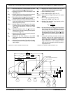
• The horizontal center of gravity of the Second Unit
Body (SUB) is rearward of L
min
† for the appropriate
vehicle description in the chart below. Lmin does not
apply to a SUB of 120 lb or less when installed rearward
of the front seats and forward of the centerline of the
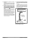
rear axle. (Do not restrict the E-Series seat travel and
provide seatback clearance to obtain the torso angle
as shown in Figure C page 32).
• The horizontal center of gravity for the SUB is:
– At or forward of the rear axle centerline. The
vertical center of gravity for the completed vehicle
at Unloaded Vehicle Weight + 400 lb passenger load
CGv (Equation A) must not exceed 36.0 inches,
when measured from the ground.
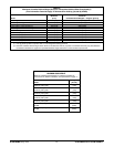
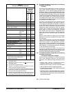
– Behind the rear axle centerline. The vertical center
of gravity for the completed vehicle at Unloaded
Vehicle Weight + 400 lb passenger load must
fall within the appropriate range determined from
Table E, page 16. The value of CGh (Equation B),
which approximates the horizontal center of gravity
of the completed vehicle, is used in Table E, to
determine the vertical center of gravity limits for the
completed vehicle. The value CGv (Equation A),
which approximates the vertical center of gravity
of the completed vehicle, must fall within the
appropriate range determined from Table E.
105 (Continued Next Page)
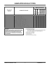
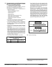
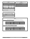
HORIZONTAL CENTER OF GRAVITY
FORWARD LIMIT
Wheelbase L
min
Vehicle Millimeter [inch] Millimeter [inch]
E-250 3505 [138] 1524 [60]
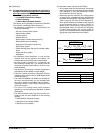
EQUATION A
CG
v
=
CG
vb
W
b
+ CG
vc
W
c
+ 25P
W
t
CG
h
=
W
t
(
W
rb
+ W
rc
+
)
x WB
(
)
P x CG
hp
WB
EQUATION B
† L
min
= the minimum horizontal center of gravity of the
SUB measured in inches rearward from the centerline
of the front axle.