


E-SERIES (May, 2004)10
E-SERIES (May, 2004) 11
STATEMENTS OF CONFORMITY
102 The statements below are applicable to all incomplete
vehicle types except the Basic (Stripped) Chassis:
This vehicle, when completed, will conform to Standard
102, Transmission Shift Lever Sequence, Starter
Interlock, and Transmission Braking Effect, if no
alterations or adjustments are made to the transmission,
shift cable, transmission outer shift lever, shift cable
bracket, vacuum tubes, vacuum pump system, brake-
shift interlock system, starter interlock system, wiring
circuit from the interlock switch to the power source, and
transmission gear selector indicator (PRNDL).
If an auxiliary transmission is added to this vehicle, it
must conform to the requirements of this Standard.
102 The statements below are applicable to the following
incomplete vehicle type:
• E-Series Basic (Stripped) Chassis
This vehicle, when completed, will conform to Standard
102, Transmission Shift Lever Sequence, Starter
Interlock, and Transmission Braking Effect if:
• No alterations or adjustments are made to the
transmission, shift cable, transmission outer shift
lever, shift cable bracket, vacuum tubes, vacuum
pump system, brake-shift interlock system, the starter
interlock system, and wiring circuit from the interlock
switch to the power source.
• The E-Series Basic (Stripped) Chassis is equipped
with a temporary transmission gear selector indicator
(PRNDL) which must be replaced with the cluster and
transmission gear selector indicator (PRNDL) that is
shipped with the vehicle in the dunnage box and must
be installed and adjusted following the instructions
and specications shown in the gure below.
If an auxiliary transmission is added to this vehicle, it
must conform to the requirements of this Standard.
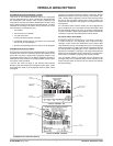
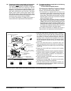
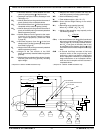
1. Route the cable after the instrument cluster is installed in
the vehicle. Do not kink the cable. Do not bend the cable
to a radius less than 4.5 inches. Route the cable from
the cluster in a counter-clockwise direction, under the
steering column, using the screw provided. Do not wrap
the cable around the steering column. The steering column
shroud installation should not affect the cable routing
or function.
2. Pull on the cable end loop for a functional check. The
cable should operate with a similar effort as required prior
to routing. Then place the cable loop on the shift lever
retainer pin.
3. Rotate the column shift lever clockwise until it bottoms
out in rst gear.
4. Rotate the column shift lever counter-clockwise 3 detents for
Overdrive “Oval D” position for TorqShift™ transmissions.
5. Install a 3 pound weight, as dened in this illustration, on
the end of the column shift lever.
6. Center the pointer in the middle of the “Oval D” position by
rotating the thumb wheel.
7. Remove the 3 pound weight. The pointer must be within
the tolerances as dened in this illustration.
8. After the steering column shrouds are installed, the
transmission gear selector indicator (PRNDL) system must
be checked for proper operation.
INSTALLATION OF GEAR SELECTOR INDICATOR (PRNDL) FOR E-SERIES BASIC (STRIPPED) CHASSIS
0
0
0
0
0
0
18
H
0
0
0
0
50
60
70
80
90
100
10
20
30
40
0
M
PH
U
N
LE
A
D
E
D
F
U
E
L
O
NL
Y
BRAKE
SERVIC
E
E
NG
I
N
E
S
O
O
N
F
H
C
E
P
R
N
1
INSTRUMENT
CLUSTER
CABLE
STEERING
COLUMN
CABLE
THUMB WHEEL
COLUMN SHIF
T
LEVER
FRONT OF
VEHICLE
CABLE RETENTION
BRACKET
SHIFT LEVER
RETAINER PI
N
N800705 SCRE
W
TORQUE 20-29 IN.LB
.
[ ] ALL DIMENSIONS ARE INCHES
3.0-3.5 LB. WEIGHT
HAND TOOL
[2.375] ± 0.25 DIA.
(PRNDL)
HOLE: [1.125] DIA.
X [2.188] 0.25 DEEP
(PRNDL) ADJUSTMENT TOLERANCE
+
+
RIGHT LIMITLEFT LIMIT TARGET
D
±