


SPSx51 Modular GPS Receivers User Guide 145
GSOF Messages B
• Signal-to-noise ratio (SNR) of L1 signal
• Signal-to-noise ratio (SNR) of L2 signal
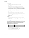
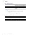
UTC
This message describes current time information. It contains the following data:
• GPS time, in milliseconds of GPS week
• GPS week number
• GPS to UTC time offset, in seconds
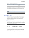
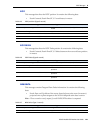
Table B.12 SV detail (Type 14 record)
Field Item Type Value Meaning
0 Output record
type
Char 0Eh Detailed satellite information output record
1 Record length Char 1 + 8×(number of SVs) Bytes in record
2–9 Number of SVs Char 00h-18h Number of satellites included in record
1
1
Includes all tracked satellites, all satellites used in the position solution, and all satellites in view.
The following bytes are repeated for Number of SVs
PRN Char 01h-20h Pseudorandom number of satellites (1–32)
Flags1 Char See Table B.21 First set of satellite status bits
Flags2 Char See Table B.22 Second set of satellite status bits
Elevation Char Degrees Angle of satellite above the horizon
Azimuth Short Degrees Azimuth of satellite from True North
SNR L1 Char dB * 4 Signal-to-noise ratio of L1 signal (multiplied
by 4)
2
2
THe SNR L1 and SNR L2 items are set to zero for satellites that are not tracked on the current frequency.
SNR L2 Char dB * 4 Signal-to-noise ratio of L2 signal (multiplied
by 4)
2
Table B.13 UTC (Type 16 record)
Field Item Type Value Meaning
0 Output record type Char 10h
1 Record length Char 09h Bytes in record
2–5 GPS millisecond of
week
Long msecs Time when packet is sent from the receiver, in GPS
milliseconds of week
6–7 GPS week number Short number Week number since start of GPS time
8–9 UTC offset Short seconds GPS to UTC time offset
10 Flags Char See Table B.19 Flag bits indicating validity of Time and UTC offsets