


53
6 F 8 A 0 9 3 4
8. Parameter Settings
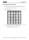
8.1 Parameter Setting Items
To check or change each constant of the converter, first select the desired setting item described in 7.3.2
“Setting and Calibration.”
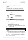
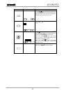
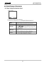
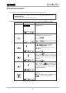
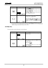
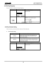
Proceed as follows for settings in the setting mode.
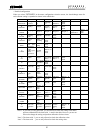
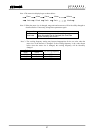
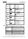
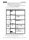
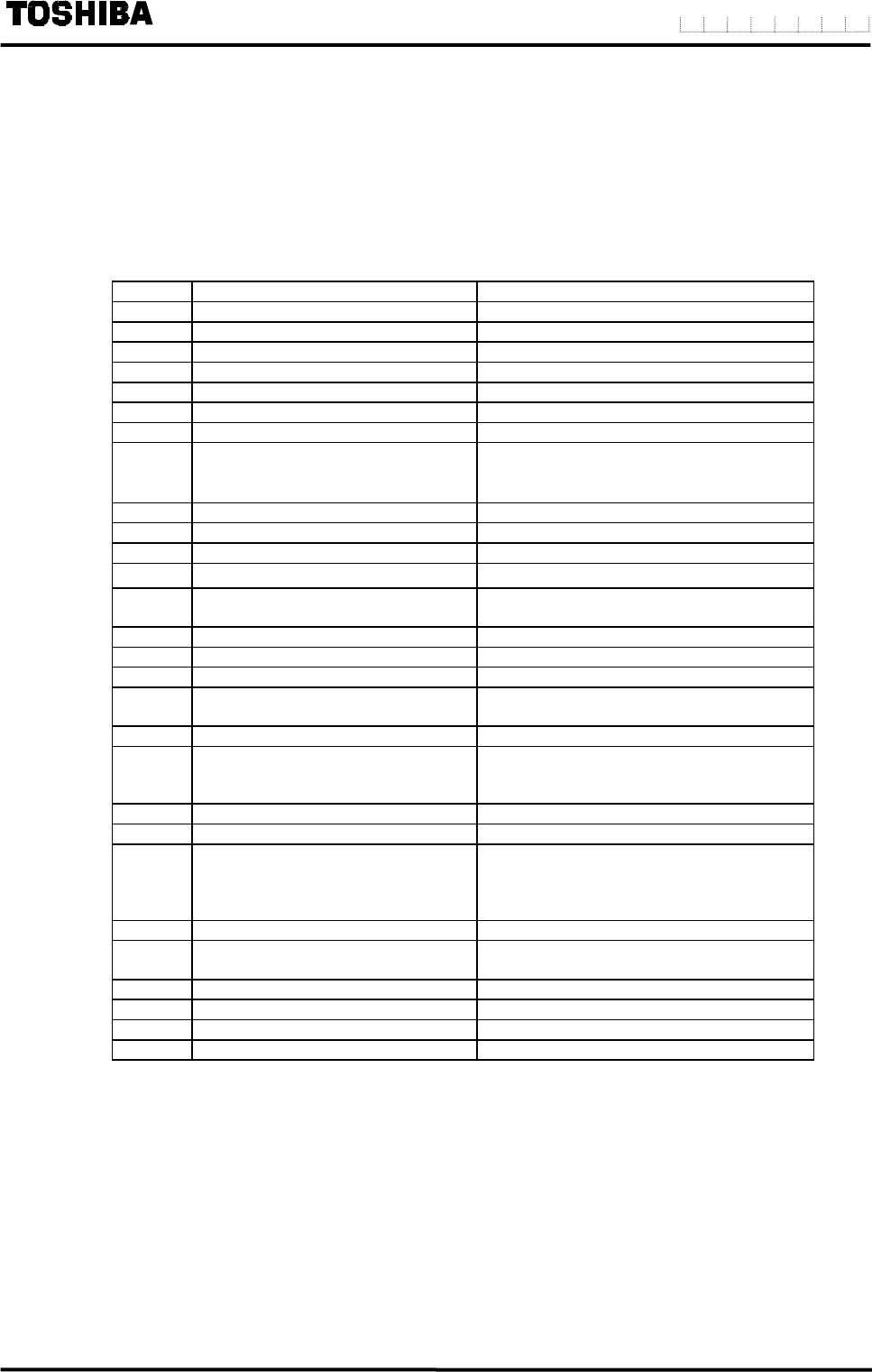
No. Function item Display example
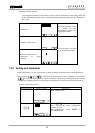
8.2.2 Exciting current EXC CUR
8.2.3 Meter size SIZE
8.2.4 Exciting frequency EXC FREQ
8.2.5 Flow direction FLOW DIR
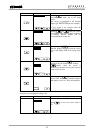
8.2.6 Display1,2 DSPL1 / DSPL2
8.2.7 Custom value CS VAL
8.2.8 Custom unit CS UNIT
8.2.9 Range (Span)
R TYPE,
R1( R4),
R HYS
8.2.10 Damping value DAMPING
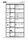
8.2.11 Limit rate, Limit time LIM RATE / LIM TIME
8.2.12 Low cut value CUT VAL
8.2.13
Display low cut
DSPL SET
8.2.14
Still water zero point
Adjustment
ZERO ADJ
8.2.15 Manual zero MANUAL
8.2.16 Output at alarm occurrence ALM 4-20
8.2.17 Output low limit LOW LIM
8.2.18 Digital output
DO1 FUNC, DO2 FUNC,
DO1 STAT, DO2 STAT
8.2.19 Digital input DI FUNC, DET LVL
8.2.20
Count rate,
Pulse width setting mode,
Pulse width
CNT RATE, PLS MODE,
PLS WID
8.2.21 Preset count value PRST VAL
8.2.22 Preset output mode OUT MODE
8.2.23
High / Low alarm limit,
HH (High high)
LL (Low low) alarm limit
H SET / H VAL
L SET / L VAL
HH SET / HH VAL
LL SET / LL VAL
8.2.24 Self check SELF CHK
8.2.25 Fix output
FIX SET, CUR VAL,
PLS VAL
8.2.26 Password PASSWORD
8.2.27 LCD adjustment LCD ADJ
8.2.28 Swtich position SW POSN
8.2.29 Communication PROFIBUS