


32
6 F 8 A 0 9 3 4
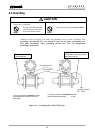
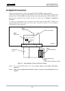
5.5 Digital I/O Connections
Digital I/O terminals consist of contact output terminals (DO1 and DO2), voltage signal input
terminal (DI), and signal common terminal (COM). Each terminal (DO1, DO2 and DI) is isolated from
internal circuits. Terminal (COM) is the signal common for the other three terminals (DO1, DO2 and DI).
Functions can be assigned for each terminal with the LCD control keys. See Chapter 10, “Digital I/O
Functions.”
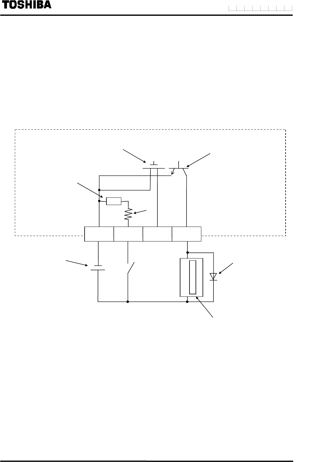
To connect an electromagnetic relay or counter to the contact output terminal (DO1 or DO2), put a
surge-absorbing diode into the input circuit of the relay or counter. See Figure 5.3 for an example of
electromagnetic counter connection.
Figure 5.3 Electromagnetic Counter Connection Example
Note 1: Use a surge-absorbing diode of the rating: current rating 1A and voltage rating 200 V
minimum.
Note 2: When a power supply-built-in electronic counter is used, the serge-absorbing diode is not
required.
Note2
Solidstate relay
Transistor open collector
COM DI DO2 DO1
Resistor
Note2
Photo-coupler
Note1
Surge-absorbing diode
Power supply
24 V dc
Electromagnetic counter
Note2
(Power supply-built-in electronic counter)
Converter