


Engine Operating Guidelines
DPSG,RG34710,108 –19–08JAN02–1/2
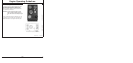
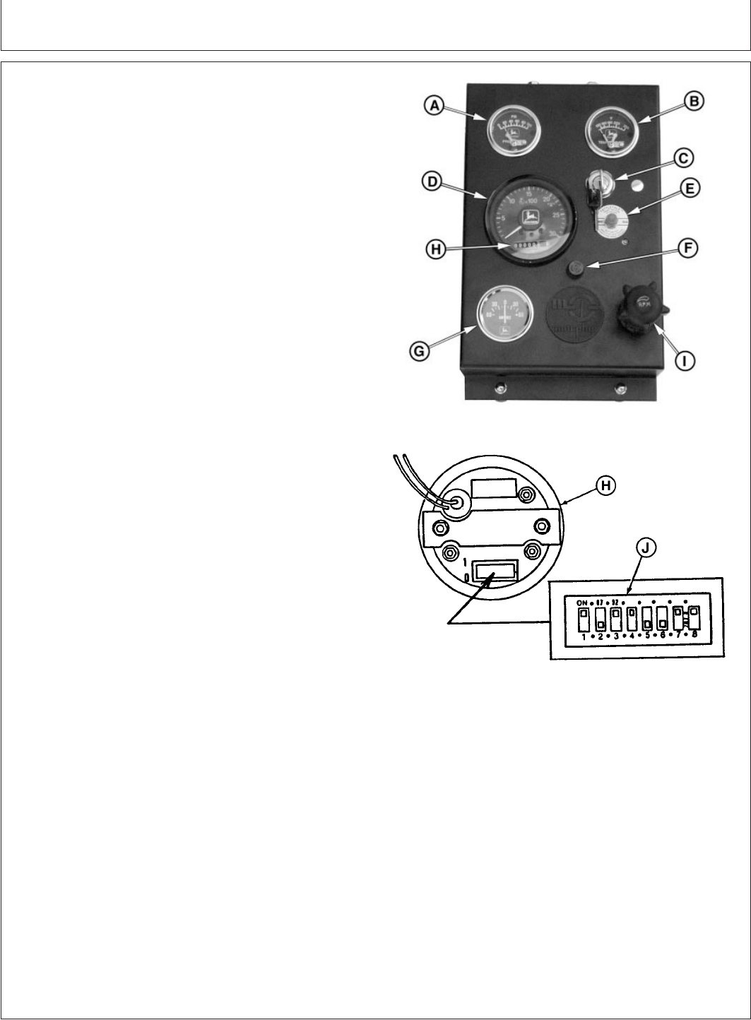
Instrument (Gauge) Panel (North America)
RG11299B –UN–17AUG00
North American Instrument Panel
RG10607 –UN–19OCT99
Hour Meter And Tachometer Codes
A—Oil Pressure Gauge
B—Coolant Temperature Gauge
C—Key Switch
D—Tachometer
E—Reset (Safety) Switch
F—Fuse Holder (14 Amp Fuse)
G—Ammeter
H—Hourmeter
I—Hand Throttle
J—Tachometer Binary Code
All controls and gauges are optional equipment for John
Deere OEM Engines. They may be provided by the
equipment manufacturer instead of John Deere. The
following information applies only to those controls and
gauges provided by John Deere.
IMPORTANT: Any time an electric gauge or meter
does not register correctly, replace it
with a new one. Do not attempt to repair
it.
Following is a brief description of the components on the
instrument (gauge) panel:
A—Oil Pressure Gauge - This gauge indicates oil
pressure. It also has an adjustable electrical contact which
activates the safety switch when oil pressure goes below
the pressure set point. This will automatically stop the
engine.
B—Coolant Temperature Gauge - This gauge indicates
coolant temperature. It also has an electrical contact
which activates the safety switch when coolant
temperature goes above the temperature set point. This
will automatically stop the engine.
C—Key Switch - The key switch is used to start and stop
the engine. A key is required to operate the switch so as
to prevent unauthorized operation of the engine.
D—Tachometer - The tachometer indicates engine speed
in hundreds of revolutions per minute (rpm).
E—Safety Switch (Reset Button) - The safety switch
de-energizes the fuel shut-off solenoid or injection rack
puller to stop the engine, if one or more conditions are
met:
• Low or no oil pressure
• High coolant temperature
• Low crankcase oil level (if equipped with engine oil level
switch)
• High crankcase oil level (if equipped with engine oil
level switch)
15-2
110306
PN=46
Continued on next page