


Lubrication & Maint./2000 Hour/24 Month
DPSG,RG41165,137 –19–16JAN02–1/5
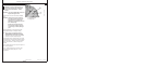
Check and Adjust Valve Clearance
RG7408 –UN–06AUG96
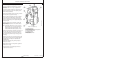
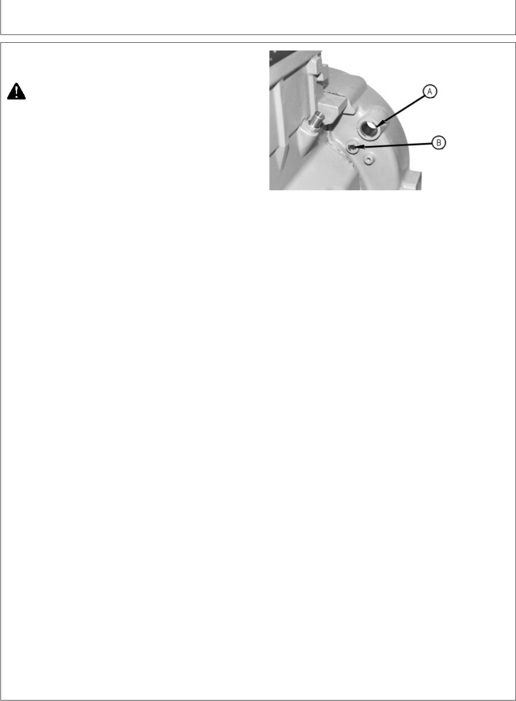
Flywheel Housing Timing Holes
A—Timing/Rotation Hole
B—Timing Pin Hole
CAUTION: To prevent accidental starting of
engine while performing valve adjustments,
always disconnect NEGATIVE (—) battery
terminal.
IMPORTANT: Valve clearance MUST BE checked and
adjusted with engine COLD.
1. Remove rocker arm cover and crankcase ventilator
tube.
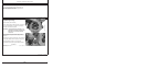
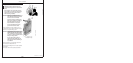
IMPORTANT: Visually inspect contact surfaces of
valve tips and rocker arm wear pads.
Check all parts for excessive wear,
breakage, or cracks. Replace parts that
show visible damage.
Rocker arms that exhibit excessive
valve clearance should be inspected
more thoroughly to identify damaged
parts.
2. Remove plastic plugs or cover plate from engine
timing/rotation hole (A) and timing pin hole (B).
NOTE: Some engines are equipped with flywheel
housings which do not allow use of an engine
flywheel rotation tool. These engines may be
rotated from front nose of engine, using JDG966
Crankshaft Front/Rear Rotation Adapter.
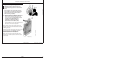
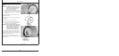
3. Using JDE83 or JD81-1 Flywheel Turning Tool, rotate
engine flywheel in running direction (clockwise viewed
from front) until No. 1 cylinder is at TDC compression
stroke. Insert JDG1571 or JDE81-4 Timing Pin in
flywheel.
If No.1 cylinder rocker arms are loose, the engine is at
No. 1 TDC compression.
If No. 1 cylinder rocker arms are not loose, rotate
engine one full revolution (360°)toNo.1TDC
compression.
40-10
110306
PN=103
Continued on next page