


Service as Required
RG,RG34710,5601 –19–07JAN02–1/1
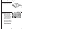
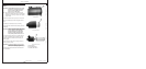
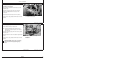
Checking Fuses In Instrument Panels
RG4493 –UN–14DEC88
North American ( —1998) Standard Instrument Panel Shown
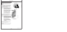
RG4496A –UN–01JUN01
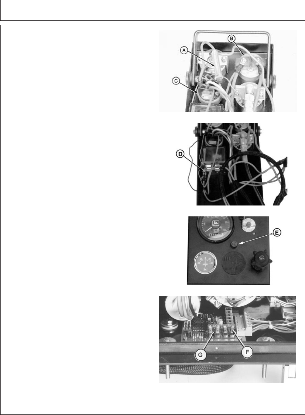
North American ( —1998) Standard Instrument Panel Shown
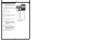
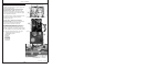
RG11937 –UN–17OCT01
North American (1999— ) Instrument Panel Shown
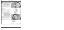
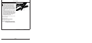
RG12067 –UN–29JAN02
VDO Instrument Panel
A—25 Amp Fuse
B—Ammeter
C—Key Switch
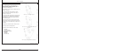
D—14 Amp Fuse
E—Fuse Holder
F—10 Amp Fuse
G—Spare Fuse
The following instructions apply to engines equipped with
John Deere instrument panels.
1. On Engines With The North American Standard
Instrument Panel ( —1998), check the fuse (A)
between the ammeter (B) and key switch (C) located
on back side of instrument panel. If defective, replace
with an equivalent 25-amp fuse.
Also check the fuse (D) mounted on the bottom of the
magnetic safety switch. If defective, install an
equivalent 14-amp fuse.
2. On later (1999— ) North American Standard
Instrument Panels, check the fuse in fuse holder (E)
on front face of instrument panel. Replace as
necessary with an equivalent 14-amp fuse.
3. For VDO Instrument Panels, the fuse is located on
the electronic control card inside the panel’s rear
access cover. Remove cover and check fuse (F). If
defective, replace with a 10-amp fuse. There is a spare
fuse (G) available on the card in the “SPARE” terminal.
NOTE: For main electrical system fuses, see engine
wiring diagrams later in this manual in
Troubleshooting Section.
45-9
110306
PN=114