


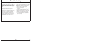

Troubleshooting
DPSG,RG41165,126 –19–19JUN00–1/1
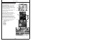
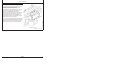
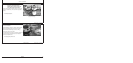
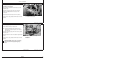
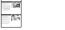
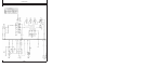
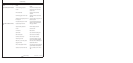
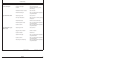
Engine Wiring Diagram Legend (Standard Instrument Panel For North America)
A1 — Speed Control Unit
B1 — Magnetic Speed Sensor
B2 — Coolant Temperature Sensor
B3 — Oil Pressure Sensor
F1 — Starting Circuit Fuse (14 amp)
F3 — Fuse (Early Models)
1
G1 — Battery
G2 — Alternator
H1 — Coolant Temperature Indicator Lamp
H2 — Oil Pressure Indicator Lamp
H3 — Alternator Indicator Lamp
K1 — Starter Relay
M1 — Starter Motor
P1 — Coolant Temperature Gauge
P2 — Oil Pressure Gauge
P3 — Crankcase Oil Level Switch/Gauge
P4 — Tachometer
1
P5 — Hourmeter (Early Models)
2
P6 — Ammeter
R1 — Resistor (48 ohm)
3
S1 — Key Switch
S2 — Magnetic Safety Switch—North American
Auto Override Module—European (Saran)
W1 — Ground on K1 Starter Relay Mounting Stud
Y1 — Starter Solenoid
Y2 — Fuel Shut-off Solenoid
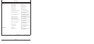
BLK — Black
BLU — Blue
BRN — Brown
DK BLU — Dark Blue
GRN — Green
ORG — Orange
PUR — Purple
RED — Red
YEL — Yellow
1
P4 tachometer has a built-in hourmeter. On some earlier engines,
a separate hourmeter (P5) and fuse (F3) were used.
2
P4 tachometer has a built-in hourmeter. On some engines, a
separate hourmeter (P5) and fuse (F3) are used.
3
Later harnesses have two parallel 100 ohm resistors for the
alternator.
50-3
110306
PN=122