


36 TRACKER950 CHARTPLOTTER Installation and Operation Manual
NAVMAN
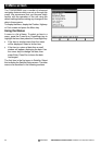
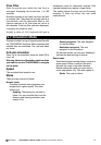
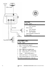
Power/NMEA cable
Pin Wire Signal
S Black Connect with 1 (Ground)
1 Black Ground, Power negative
2 Brown +13.8 V DC out for external MOB switch,
protected
3 White NMEA out, to autopilot/radar
4 Blue NMEA in/out, depth sounder input
5 Red Positive power in, 11 to 16.6 V DC
6 Orange External MOB switch in
7 Yellow Auto Power in, 12 V for Auto Power
8 Green External beeper out, 12 VDC, 250 mA
Note: shield is connected to pin 1, black wire
S
1
2
3
4
5
6
7
8
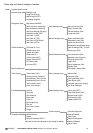
GPS or DGPS
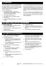
Fuel cable
Power/NMEA cable
Fuel cable
Pin Wire Signal
1 Black Ground / Fuel Transducer
2 - Fuel Transducer
3 White Ground
4 - Fuel Transducer
5 Red Do not connect
6 - Fuel Transducer
7 Yellow Differential Correction (IN)
8 Green Spare
Fuel
Transducer
1
3
5
7
8
8
7
6
5
4
3
2
1