


30 TRACKER950 CHARTPLOTTER Installation and Operation Manual
NAVMAN
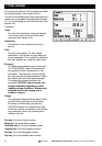
Backlight
Backlight brightness, 16 Levels
Local Time Ofst
The difference between local time and UTC (GMT).
You must change Local Time Ofst when daylight
saving time starts and ends.
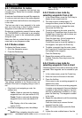
9-1 General Setup
Map Datum
128 chart datums are provided. The satellite
derived positions displayed on the TRACKER950
can be adjusted to match your local paper charts
by selecting the appropriate datum for your region.
North Reference
The options are True or AutoMag.
Map Orientation
The options are:
North up: North is always at the top of a
chart display.
Projected Track up: The chart is
automatically rotated so that the boat
direction is to the top of the screen. A small
square appears in the upper right corner of
the LCD, indicating the direction of North.
This mode is useful for navigating narrow
harbours or rivers.
Velocity Averaging
The TRACKER950 can show instantaneous speed
or speed averaged over a selected period. The
options are OFF, 20 seconds and 60 seconds. The
9-2 Navigation Setup
COG damping is also derived from this setting.
Projected Course
The TRACKER950 can estimate your course
based on your current speed and heading. It can
display this course as a solid line from the boat
position. The length of the line is how far you will
travel in a specified time and the options for this
Projected Course time are 2 minutes, 10 minutes,
30 minutes, 1 hour and 2 hours or OFF.
User-definable fields
The Highway screen displays four user-definable
fields: User Data 1, User Data 2, User Data 3 and
User Data 4. The choices for each field are VMG,
CTS, ETA, TTG, XTE, STR , Depth, Fuel Economy,
Range, Scale or CDI scale.
User Data 1 and User Data 2 are also displayed
on the Underway screen.
NMEA Output
Enable/Disable the NMEA0183 output for the
autopilot or radar.
Language
Select the language for the screens. The options
are Dutch, English, French, German, Italian,
Portuguese, Spanish and Swedish.
CDI Scale
The CDI Scale controls the Course Deviation
Indicator (CDI) which is displayed on the Highway
screen when navigating to a point (see section 5).
Set the CDI Scale to the maximum distance that
you would like the boat’s path to deviate from the
original plotted course. The options are 0.05, 0.1,
0.2, 0.5, 1.0, 2.0, 4.0 and 10.0 distance units.
Distance Units
Options are nautical miles, statute miles or
kilometres.
Speed Units
Options are knots, miles per hour and kilometres
per hour.
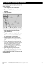
9-3 CDI/Units/Alarms Setup
Depth Units
Options are feet, fathoms or metres.
Arrival Radius Alarm
When the Arrival Radius alarm is enabled it gives
an alarm:
a when the boat comes within this distance of
a waypoint, (either a normal or danger
waypoint)
b or when the boat is navigating a route to a
waypoint and the boat passes the waypoint
To enable the alarm, enter an Arrival Radius
distance (up to 9.99 distance units).
To disable the alarm, set the Arrival Radius
value to OFF.