


Loading and storing
232
X
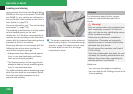
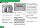
Attach cover caps (Y page 230) and lock
them.
X
Store key and Allen wrench back into the
storage well (Y page 326).
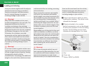
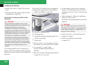
Adjusting the clamping widths of the
crossbars
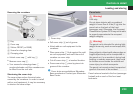
G
Warning!
Only install the crossbars at the exact
locations designated on the roof rails. The
designated locations for the front
crossbars are between the markings
engraved on the inside of the roof rails. The
designated locations for the rear crossbars
are between the gaps on the roof rails.
Otherwise, the crossbars, mounted
accessories and the objects attached to
them could come loose from the vehicle
causing an accident, thereby injuring you
and other persons and/or causing damage
to property, including damage to your
vehicle.
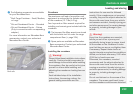
The clamping widths of the crossbars are
factory set for your vehicle. These clamping
widths are solely intended for the designated
positions.
Only install the crossbars at the designated
locations and pay attention to the stickers
3 FRONT and REAR (Y page 231).
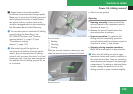
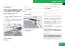
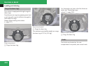
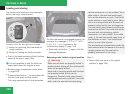
4
Screw for clamping claw
5
Clamping claw
b
Screws for adjusting clamping width (2 in
total for each side)
c
Cover strip
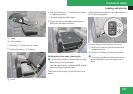
X
Pull cover strip c out of groove until you
see screws b on each end of the crossbar.
X
Turn screws b on both sides
counterclockwise approximately 2
rotations.
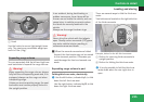
X
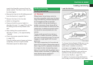
Place the crossbar at designated locations
(Y page 231) on roof rails.
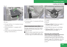
X
On both sides, make sure the clamping
claws 5 lie flush against the roof rails. If
necessary, pull out or push in the clamping
claws 5.
X
Tighten screws b. Observe a tightening
torque of 4 lb-ft (6 Nm).
The width of the clamping claws is correctly
adjusted.
G
Warning!
Have the tightening torque checked after
mounting the crossbars. The screws could
come loose if they are not tightened to a
torque of 4 lb-ft (6 Nm).
X
Press cover strip c piece by piece into
groove of crossbar.
X
Install the crossbars as described
(Y page 229).
Controls in detail