


72
Reassembly
KohlerEngines.com 20 690 01 Rev. F
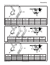
Install Spark Plug
1. Check gap using wire feeler gauge. Adjust gap to
0.76 mm (0.03 in.).
2. Install plug into cylinder head.
3. Torque plug to 27 N·m (20 ft. lb.).
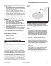
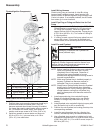
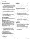
Install Heat Defl ector, Carburetor, Linkage and Air
Cleaner Base
1. If carburetor mounting stud was removed, reinstall it
in outer cylinder location (closest to head). Use an
E5 Torx
®
socket or two nuts tightened together, and
turn stud in until tight.
2. Make sure all gasket surfaces are clean and free of
any nicks or damage.
3. Install a new intake gasket onto carburetor stud,
then install heat defl ector. Curved section should be
down, toward engine. If defl ector contains a molded
protruding point, it should be towards back inserted
into intake port. Be sure protruding point goes
through large hole in gasket, to keep it aligned.
4. Models with one screw and one mounting stud only:
Insert a 3/16” diameter rod, approximately 4” long,
into open mounting hole in heat defl ector to serve as
a temporary alignment pin. Be careful not to force
rod or damage threads.
5. Install a new carburetor gasket onto mounting
stud(s) and/or alignment pin.
6. Attach choke and throttle linkages to carburetor and
install carburetor assembly. If governor lever was not
disconnected, slide it onto governor shaft with lever
up.
7. If carburetor has a fuel solenoid, fasten ground lead
to crankcase boss, with toothed washer between
eyelet terminal and boss. Torque screw to 8.0 N·m
(70 in. lb.). Connect solenoid power lead to wiring
harness and secure with a tie strap.
8. Connect fuel line to carburetor and secure with a
hose clamp.
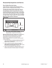
9. Install air cleaner base (with fuel pump attached, if
equipped).
a. Install a new air cleaner base gasket. Check two
metal spacers are in air cleaner base mounting
holes and install base onto stud(s), and or
alignment pin. Make sure upper mounting tab is
positioned above closure plate boss. Install nut(s)
and fi nger tighten.
b. Models with one screw and one mounting stud
only: Apply hand pressure to keep parts from
shifting, then carefully remove alignment pin and
install DRY long M6 thread forming screw. DO
NOT OIL. Check to make sure all gaskets are still
in proper position.
c. Torque nut(s) to 5.5 N·m (48 in. lb.). Torque screw
to 8.0 N·m (70 in. lb.) into a new hole, or 5.5 N·m
(48 in. lb.) into a used hole, do not over tighten.
An M6 screw for upper tab will be installed when
blower housing is mounted.
10. Attach breather hose to valve cover and air cleaner
base.
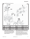
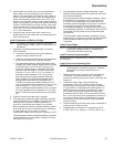
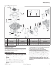
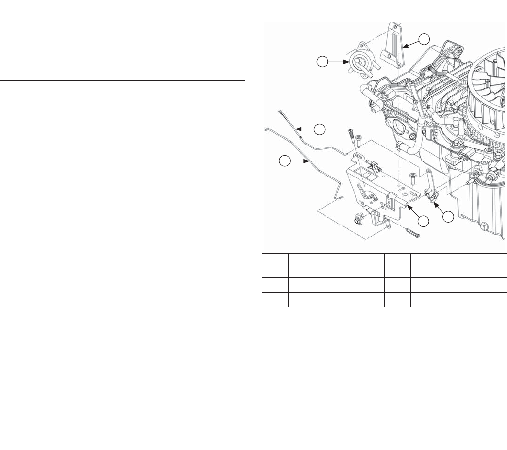
Install and Adjust Governor Lever
Speed Control Bracket Details
F
B
D
C
E
A
A Governor Lever B
Speed Control
Bracket
C Choke Linkage D Throttle Linkage
E Fuel Pump Bracket F Fuel Pump
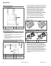
NOTE: It is recommended a new governor lever be
installed whenever removal is performed.
1. Install governor lever onto governor shaft with lever
section up. Connect throttle linkage using black
linkage bushing.
2. Move governor lever toward carburetor, to limit of its
travel (wide-open throttle) and hold in this position.
Do not apply excessive pressure, fl exing or distorting
linkage. Grasp cross shaft with a pliers, and turn
shaft counterclockwise as far as it will go. Torque nut
to 7.0-8.5 N·m (60-75 in. lb.).
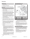
Mounting Speed Control Bracket
1. Attach governor spring to governor lever and throttle
lever of speed control bracket, in original holes. If
holes were not marked during disassembly, refer to
Governor Spring Location charts. Connect choke
linkage from carburetor to actuating lever of speed
control bracket.
2. Attach speed control bracket to mounting locations
on engine with M6 screws. Position bracket as
marked during disassembly. Torque screws to
11.0 N·m (95 in. lb.) into new holes, or 7.5 N·m
(65 in. lb.) into used holes.