30
Fuel System
KohlerEngines.com 20 690 01 Rev. F
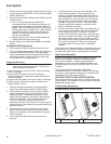
Throttle Control Installation
1. Loosen two cable clamp screws on speed control
bracket assembly.
2. Move application throttle control lever to maximum
full (fast) throttle position, and then move it back
3/16" or 4.75 mm. Insert cable boden wire into
throttle control lever on control plate.
3. Position throttle cable under cable clamp.
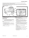
4. Early Models: Early models use a single alignment
hole to set engine RPM. Align hole in throttle lever
with hole in speed control bracket by inserting a
pencil or 6.35 mm (1/4 in.) drill bit.
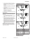
Later Models: Later models utilize a new design
control assembly, identifi ed by two opposing
alignment holes (close to throttle lever pivot), instead
of one. Based upon intended high speed (RPM)
setting, throttle cable adjustment must be made
matching hole in control lever with appropriate
alignment hole. Use lower (left side) hole for high-
speed settings 3000 RPM and above. Use upper
(right side) hole for high-speed settings less than
3000 RPM. Move throttle lever to align hole in lever
with appropriate hole in control bracket. Insert a
pencil or a 6.35 mm (1/4 in.) drill bit to hold in
position.
Current Models: Current models use a new control
assembly, identifi ed by three alignment holes (close
to throttle lever pivot). Based upon intended high-
speed (RPM) setting, throttle cable adjustment must
be made by matching hole in control lever with
correct alignment hole. Use appropriate hole for
corresponding high-speed settings. Move throttle
lever to align hole in lever with correct hole in control
bracket. Insert a pencil or a 6.35 mm (1/4 in.) drill bit
to hold in position.
5. Pull on outer shield of throttle control cable to
remove any slack. Tighten cable clamp securely.
6. Move application throttle lever to slow position, then
to full throttle. Check engine control to ensure it
stops against stop screw, which means it is properly
set.
Choke Control Installation
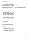
1. Connect choke cable boden wire to engine choke
control lever on speed control bracket assembly.
2. Position choke cable under cable clamp.
3. Push/move choke control to off position in
application panel until it bottoms, then pull it back
approximately 1/16 in.
4. Push on choke cable, ahead of clamp on engine
control plate, until choke lever stops. Do not force.
Then tighten cable clamp screw.
5. Move choke control until it stops (on position). Check
that choke link cannot be moved towards carburetor
by applying fi nger pressure on lower link/lever below
engine control plate. If choke link moves, readjust by
following steps 3 and 4.
6. Push/move choke control in/down until it bottoms.
Choke lever and link should be to right at end of its
travel, with linkage free so engine does not run on
partial choke.
Starting an Engine Equipped with Separate Control
Cables
1. Place throttle control midway between slow and fast
positions. Place choke control into on position.
2. Start engine.
3. For a Cold Engine – Gradually return choke control
to off position after engine starts and warms up.
Engine/equipment may be operated during warm up
period, but it may be necessary to leave choke
partially on until engine warms up.
4. For a Warm Engine – Return choke to off position as
soon as engine starts.
Changing High Speed (RPM) on Engines with
Separate Controls (Increase or Decrease RPM)
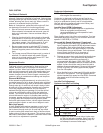
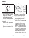
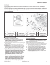
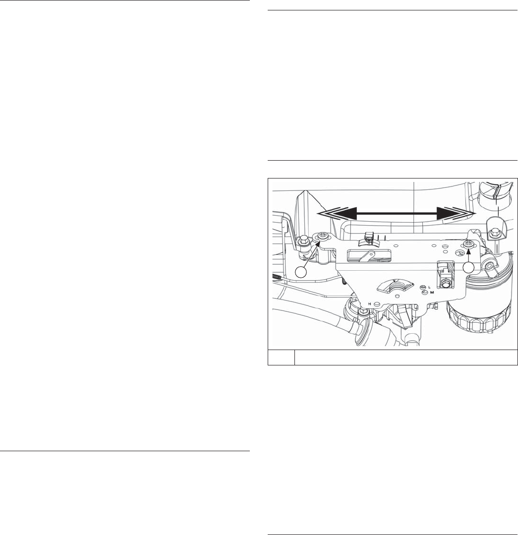
Speed Control Bracket Details
A
A
A Speed Control Bracket Mounting Screw
1. Check that governor spring and installation matches
intended high speed RPM operating range.
2. Start engine, move application throttle lever to full
throttle/fast, and loosen mounting screws of main
speed control bracket to allow repositioning.
3. To increase RPM: Move speed control bracket,
towards carburetor. To decrease RPM: Move speed
control bracket, away from carburetor. Check RPM
with a tachometer and tighten screws when correct
setting has been obtained.
4. To ensure that RPM has been obtained, move
throttle lever to low idle/slow then back to full throttle/
fast position and check RPM with a tachometer.
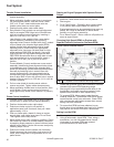
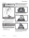
Setting Low Idle RPM
1. Move application control to slow position.
2. Using a tachometer, check RPM. Then, using a
screwdriver, turn low idle speed screw inward
(clockwise) to increase RPM, and outward
(counterclockwise) to lower RPM.


