


45
Starter System
20 690 01 Rev. F KohlerEngines.com
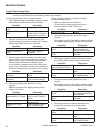
When power is applied to starter, armature rotates. As
armature rotates, drive pinion moves out on splined
drive shaft and into mesh with fl ywheel ring gear. When
pinion reaches end of drive shaft, it rotates fl ywheel and
cranks engine. When engine starts, fl ywheel rotates
faster than starter armature and drive pinion. This moves
drive pinion out of mesh with ring gear and into retracted
position. When power is removed from starter, armature
stops rotating and drive pinion is held in retracted
position by anti-drift spring.
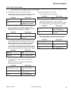
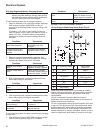
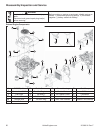
Starter Drive Service
It is not necessary to completely disassemble starter to
service drive components.
1. Disassemble retaining ring, use tool.
2 Grasp spring retainer and push it toward starter,
compressing anti-drift spring and exposing retaining
ring.
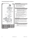
3. Holding spring retainer in retracted position,
assemble inner halves of removal tool around
armature shaft with retaining ring in inner groove.
Slide collar over inner halves to hold them in
position.
4. Thread center screw into removal tool until you feel
resistance. Use a wrench (1 1/8" or adjustable) to
hold base of removal tool. Use another wrench or
socket (1/2" or 13 mm) to turn center screw
clockwise. Resistance against center screw will tell
you when retaining ring has popped out of groove in
armature shaft.
5. Remove drive components, and drive nut (collar)
from armature shaft, paying attention to sequence. If
splines are dirty, clean them with solvent.
6. Splines should have a light fi lm of lubricant.
Relubricate as necessary with Kohler bendix starter
lubricant. Reinstall or replace drive components,
assembling them in same sequence as they were
removed.
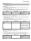
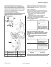
Retaining Ring Installation
1. Position retaining ring in groove in one of inner
halves. Assemble other half over top and slide on
outer collar.
2. Be certain drive components are installed in correct
sequence onto armature shaft.
3. Slip tool over end of armature shaft, so retaining ring
inside is resting on end of shaft. Hold tool with one
hand, exerting slight pressure toward starter. Tap top
of tool with a hammer until you feel retaining ring
snap into groove. Disassemble and remove tool.
4. Squeeze retaining ring with pliers to compress it into
groove.
5. Assemble inner halves with larger cavity around
spring retainer. Slide collar over them and thread
center screw in until resistance is felt.
6. Hold base of tool with a 1 1/8" wrench and turn
center screw clockwise with a 1/2" or 13 mm wrench
to draw spring retainer up around retaining ring. Stop
turning when resistance increases. Disassemble and
remove tool.
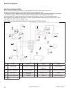
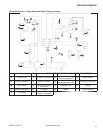
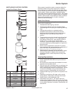
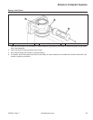
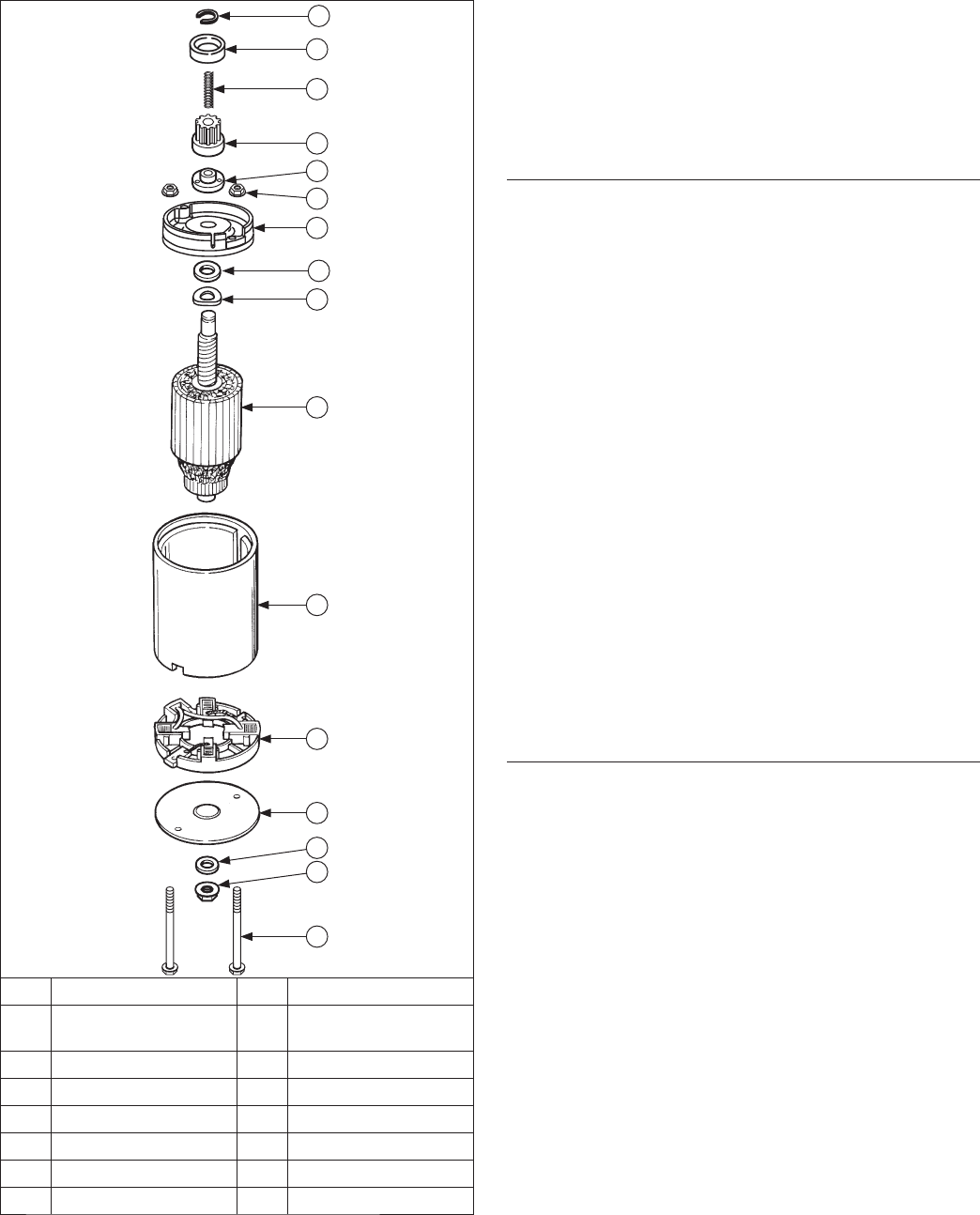
INERTIA DRIVE ELECTRIC STARTERS
Inertia Drive Electric Starter
A
B
C
D
E
F
G
H
I
J
K
L
M
P
O
N
A Thru Bolts B Hex Flange Nut
E
Brush Carrier
Assembly
F Frame Assembly
C Insulating Washer D Commutator End Cap
G Armature H Wave Washer
I Thrust Washer J Drive End Cap
K Hex Flange Nut L Drive Nut (Collar)
M Pinion N Anti-Drift Spring
O Retainer P Retaining Ring