


57
Disassembly/Inspection and Service
20 690 01 Rev. F KohlerEngines.com
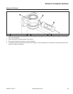
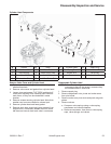
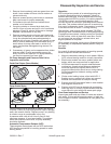
1. Remove thrust washer(s) and cam gears from cam
shafts. Later models will have a thrust washer on
exhaust side only.
2. Remove screws securing cam levers to crankcase.
Mark cam levers for proper reassembly.
3. Pull exhaust side cam shaft and slotted thrust
washer, out of crankcase.
4. If engine contains an internal drain back tube,
unhook it from oil pump and pull it out of crankcase
passage. Check for cracks, brittleness or damage.
Replace if questionable in any way.
5. Remove screws securing oil pump and intake side
cam shaft to crankcase. If a drain back tube is used,
it may be unhooked and removed separately or
together with oil pump. Carefully pull upward on cam
shaft to remove assembly from crankcase cavity. A
small rubber oil pump outlet seal on outlet of oil
pump may become dislodged during removal. Do
not lose it.
6. If necessary, oil pump can be separated from intake
side cam shaft. Provide appropriate support for
shaft, and drive out lower pin. Oil pump assembly
can then be removed from cam shaft.
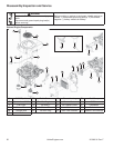
Oil Pump Assembly and Pressure Relief Valve
Inspection and Service
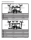
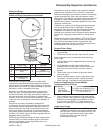
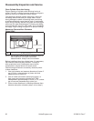
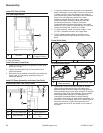
Outlet Seal Styles (Some Models)
BA
A Open Seal B Closed Seal
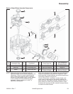
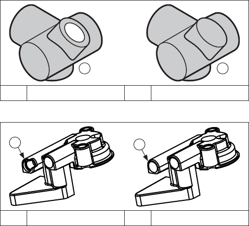
Pump Outlet Styles
A
B
A Open Outlet Seal B Closed Outlet Seal
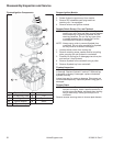
Closure plate must be removed to inspect and service
oil pump. Check oil pump and gears for cracks, damage,
wear, and smooth rotation. Replace pump if any binding
is noted or reuse is questionable in any way.
A pressure relief valve is built into oil pump to limit
maximum pressure. It is not serviceable. If a problem
exists with pressure relief valve, oil pump assembly
should be replaced.
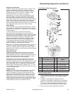
Automatic Compression Release (ACR)
These engines are equipped with an ACR mechanism.
ACR lowers compression at cranking speeds to make
starting easier.
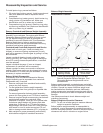
Operation
ACR mechanism consists of an actuating spring and
a pivoting fl yweight/control pin assembly, located in
exhaust side cam gear. A thrust washer and mounting
closure plate hold ACR in position. At cranking speeds
(700 RPM or lower), spring holds fl yweight in and
rounded surface of control pin protrudes above exhaust
cam lobe. This pushes exhaust valve off its seat during
fi rst part of compression stroke. Compression is reduced
to an effective ratio of about 2:1 during cranking.
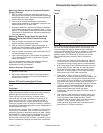
After starting, when engine speed exceeds 700 RPM,
centrifugal force overcomes force of the fl yweight spring.
Flyweight moves outward, rotating control pin to expose
the fl at surface, which is lower than cam lobe. Control
pin no longer has any effect on exhaust valve, and
engine operates at full power.
When engine is stopped, spring returns fl yweight/control
pin assembly to compression release position, ready for
next start.
Benefi ts
As a result of reduced compression at cranking speeds,
several important benefi ts are obtained:
1. Manual (retractable) starting is much easier. Without
ACR, manual starting would be virtually impossible.
2. Electric start models can use a smaller starter and
battery which are more practical for application.
3. ACR eliminates need for a spark retard/advance
mechanism. A spark retard/advance mechanism
would be required on engines without ACR to
prevent kickback which would occur during starting.
ACR eliminates this kickback, making manual
starting safer.
4. Choke control setting is less critical with ACR. If
fl ooding occurs, excess fuel is blown out opened
exhaust valve and does not hamper starting.
5. Engines with ACR start much faster in cold weather
than engines without ACR.
6. Engines with ACR can be started with spark plugs
which are worn or fouled. Engines without ACR are
more diffi cult to start with those same spark plugs.
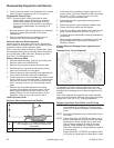
Cam Gears Inspection and Service
Inspect gear teeth and cam lobes of intake and exhaust
cam gears. If lobes exhibit excessive wear, or teeth are
worn, chipped or broken, replacement of cam gear(s) will
be necessary.