


40
Electrical System
KohlerEngines.com 20 690 01 Rev. F
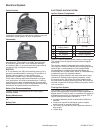
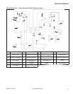
3 Amp/70 Watt Braking Stator
NOTE: Zero ohmmeter on each scale to ensure accurate readings. Voltage tests should be made with engine
running at full throttle with no load. Battery must be fully charged.
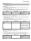
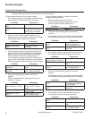
To test charging system for no charge to battery:
1. With engine running in fast setting, measure voltage
across battery terminals using a DC voltmeter.
Condition Conclusion
Voltage is more than 12.5
volts.
Charging system is OK.
Voltage is 12.5 volts or
less.
Stator or diode are
probably faulty. Continue
testing stator and diode.
2. Remove connector from rectifi er-regulator. With
engine running in fast position, measure AC voltage
across stator leads using an AC voltmeter.
Condition Conclusion
Voltage is 5 volts or more. Stator winding is OK.
Voltage is less than 5
volts.
Test stator using an
ohmmeter.
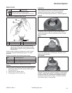
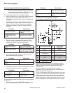
3. With charging lead disconnected from battery and
engine stopped, measure resistance from charging
lead to ground using an ohmmeter. Note reading.
Reverse leads and measure resistance again.
In one direction, resistance should be infi nity ohms
(open circuit). With leads reversed, some resistance
should be measured (about midscale on Rx1 range).
Condition Conclusion
Resistance is low in both
directions.
Diode is shorted. Replace
diode.
Resistance is high in both
directions.
Diode or stator winding is
open. Continue testing.
4. Disconnect lighting lead (yellow) from wiring
harness.
Measure resistance from lighting lead to ground
using an ohmmeter.
Condition Conclusion
Resistance is
approximately 0.15 ohms.
Stator winding is OK,
diode is open. Replace
diode.
Resistance is 0 ohms. Stator winding is shorted.
Replace stator.
Resistance is infi nity
ohms.
Stator winding or lead is
open. Replace stator.
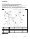
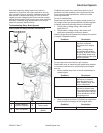
To test charging system for no lights and battery
charging (braking system):
1. Make sure lights are not burned out.
To test battery charging system go to step 4,
otherwise perform steps 2 and 3 only.
Condition Conclusion
Burned out lights. Replace.
2. Disconnect lighting lead (yellow) from wiring
harness.
With engine running in fast setting, measure voltage
from lighting lead to ground using an AC voltmeter.
Condition Conclusion
Voltage is 13 volts or
more.
Stator is OK. Check for
loose connections or
shorts in wiring harness.
Voltage is less than 13
volts.
Test stator using an
ohmmeter.
3. With engine stopped, measure resistance of stator
from lighting lead to ground using an ohmmeter.
Condition Conclusion
Resistance is
approximately 0.15 ohms.
Stator is OK.
Resistance is 0 ohms. Stator is shorted. Replace
stator.
Resistance is infi nity
ohms.
Stator or lighting lead is
open. Replace stator.
4. Disconnect braking lead (green) from wiring
harness.
With engine running in fast setting, measure voltage
from braking lead to ground using an AC voltmeter.
Condition Conclusion
Voltage is 35 volts or
more.
Stator is OK. Circuitry on
unit that grounds braking
lead is shorted.
Voltage is less than 35
volts.
Test stator using an
ohmmeter.
5. With engine stopped, measure resistance from
braking lead to ground using an ohmmeter.
Condition Conclusion
Resistance is 0.2-0.4
ohms.
Stator is OK.
Resistance is 0 ohms. Stator is shorted. Replace
stator.
Resistance is infi nity
ohms.
Stator or lighting lead is
open. Replace stator.