


PREPARA
TION 33
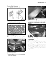
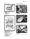
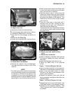
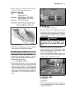
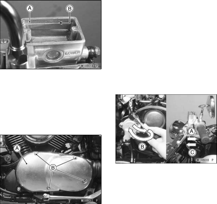
A. Clutch Fluid Reservoir
B. Upper Level Line
•
Operate the clutch lever several times.
•
If it feels spongy, there might be air in the line.
•
If necessary, bleed the air in the lines.
•
Also check for fluid leakage around the fit-
tings.
Clutch Line Air Bleeding
•
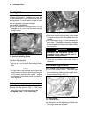
Loosen the mounting bolts to remove the al-
ternator outer cover.
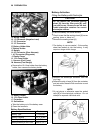
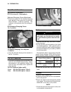
A. Alternator Outer Cover
B. Socket Bolts and Washers
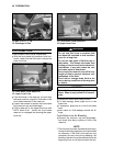
•
Remove the reservoir cap and diaphragm,
and check that there is plenty of fluid in the
reservoir.
NOTE
żThe fluid level must be checked several times
during the bleeding operation and replenished
as necessary. If the fluid in the reservoir runs
completely out any time during bleeding, the
bleeding operation must be repeated from the
beginning since air will have entered the line.
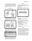
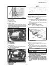
•
Attach a clear plastic hose to the bleed valve
on the clutch slave cylinder and run the other
end of the hose into a container.
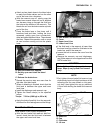
•
With the reservoir cap off, slowly pump the
clutch lever several times until no air bubbles
can be seen rising up through the fluid from
the holes at the bottom of the reservoir. This
bleeds the air from the clutch master cylinder
end of the line.
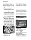
•
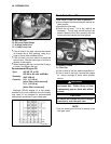
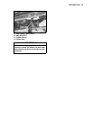
Pump the clutch lever a few times until it
becomes hard and then, holding the lever
squeezed, quickly open (turn counterclock-
wise) and close the bleed valve.
Then release the lever. Repeat this operation
until no more air can be seen coming out into
the plastic hose.
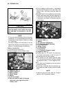
A. Hold the clutch lever applied.
B. Quickly open and close the bleed
valve.
C. Release the clutch lever.
•
When air bleeding is finished, check that the
fluid level is between the upper and lower
level lines.
•
Install the diaphragm and reservoir cap.
•
Tighten the bleed valve to the specified
torque.
Torque: 7.8 N·m (0.80 kgf·m, 69 in·lb)
•
Apply the clutch forcefully for a few seconds,
and check for fluid leakage around the fittings.
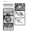
•
Apply a soap and water solution or rubber
lubricant to the body of the alternator cover
bolts for easy installation.
•
Reinstall the alternator outer cover with the
bolts and washers and tighten the bolts to the
specified torque.
Torque:
6.9 N·m (0.70 kgf·m, 61 in·lb)
•
Reinstall the front and rear shift pedals. See
“Shift Pedal” section in the Assembly chapter.
•
Reinstall the left footboard assembly. See
“Front Footboard (Left)” section in the Assem-
bly chapter.