


ASSEMBL
Y9
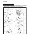
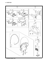
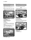
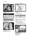
A. Right Switch Housing
B. S
crews (L = 25)
C. Harness
D. Throttle Cable (Accelerator)
E. Throttle Cable (Decelerator)
F. Holder Screw
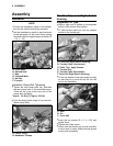
Front Brake Master Cylinder
•
Connect the right switch housing lead con-
nectors to the front brake light switch termi-
nals on the front brake master cylinder.
•
Apply silicone grease or PBC grease to the
master cylinder clamp bolts.
•
Install the front master cylinder with its clamp
and the two socket bolts (D = 6, L = 20).
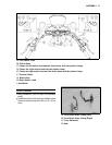
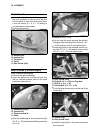
A. Front Master Cylinder
B. Punched Mark
C. Clamp
D. Socket Bolts
E. Harness
F. Front Brake Light Switch
G. Connectors and Dust Covers
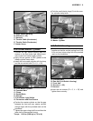
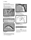
•
Position the master cylinder so that the gap
between the front and rear master cylinder
clamps aligns with the punched mark on the
handlebar.
•
Tighten the upper clamp bolt first and then the
lower bolt to the specified torque.
Torque:
8.8 N·m (0.90 kgf·m, 78 in·lb)
•
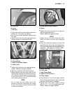
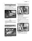
Push the small plastic plugs (2) into the mas-
ter cylinder clamp bolts.
A. Plastic Plugs
B. M
aster Cylinder
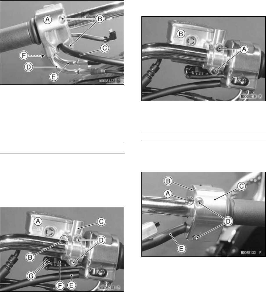
Left Switch Housing
•
Fit the two halves of the left switch housing
together so that the vertical parting line of the
front and rear halves align with the punched
mark on the handlebar.
A. Punched Mark
B. Rear Half (Left Switch Housing)
C. Front Half
D. Screws (L = 25)
E. Harness
•
Insert the two screws (D = 5, L = 25) and
tighten them securely.