


CM6000 Install Guide
Alarm and Starter System
www.firstechonline.com | www.compustar.com
Copyright 2009 Firstech, LLC.
Page 9
Jumper 3 (Parking Light to Trunk Output)
Determines the output type (not polarity) of the green/white wire on connector one (CN1). In the default
position it provides a positive (+) parking light output. To change to a positive (+) trunk output move the
jumper. A negative (-) parking light output is found on connector three (CN3) and a negative (-) trunk output is
found on connector four (CN4).
Setting Auxiliary Outputs on Connector 2
You Must Have the OP500 Option Programmer
To set auxiliary outputs on the control module involves the new Programmable Output Connector wires (POCs).
You must choose two odd pin wires on the black 18 pin connector that you are not using. For example we will
use POC 8 and 9.
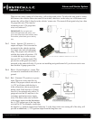
STEP 1: Plug in OP500 and use the Right or Left Arrow Button to scroll through the menu to POC 8 and POC 9 on LCD Line 1.
STEP 2: Use the Up or Down Arrow Button to change the lower number on LCD Line 2 to 10 – Auxiliary 1 or 11- Auxiliary 2.
STEP 3: Scroll up the menu to Option 4-01 and 4-02 and set the options. Please see the Option Table for details.
STEP 4: The Pro control modules have a secure auxiliary option 4-05. This requires you to tap button 4 before you tap button 2 for
Aux 1 or button 3 for Aux 2. On 1-Way remotes you must hold the Trunk and Key/Start buttons for 2.5 seconds then tap the Trunk
button for Aux 1 or the Key/Start button for Aux 2.
STEP 5: If you need to change the time settings of the outputs go to AU1 or AU2 on the OP500. LCD Line 2 is the timed output.
STEP 6: Hold the “W” Write button for 3 seconds to set all the options.
Tach Sensing
The default engine sensing mode is tach. In cold weather climates we recommend using an injector wire verses
a coil wire for tachometer sense. There are new features that adjust tach reading methods on option 2-01.
IMPORTANT: The remotes must be coded prior to setting up tach sensing. Firstech recommends using a digital
multimeter to test for tach.
STEP 1: Start the vehicle with the key. Allow time for the engine to idle down.
STEP 2: Test wire and make connection. At idle the tach wire should test between 1 to 4 Volts AC. As the
vehicle RPM’s increase the voltage on the meter will also increase. Always solder tach connections.
STEP 3: Learn tach. While the vehicle is at idle, hold the foot brake and press and hold the remote start button
on the remote control for 2.5 seconds.
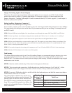
The parking lights will ash once and the siren
will chirp once to conrm a good tach signal. The
parking lights will ash two times and the siren
will chirp two times to indicate the tach did not
learn. Two seconds following the two ashes, the
number of parking light ashes will indicate the
cause of the error:
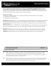
Number of
Parking Light
Flashes
Tach Error
1 Option 2-10 is not in default setting 1
2 Key is in the off position
3 Bad tach signal. Find a different wire.