


CM6000 Install Guide
Alarm and Starter System
www.firstechonline.com | www.compustar.com
Copyright 2009 Firstech, LLC.
Page 18
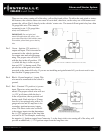
Connector 10 (CN10), 6-Pin to 6-Pin (Pre-wired Antenna Cable)
Connect your antenna cable to this port. You can only use 6 to 6 pin antenna cables. 4 to 4 or 4 to 6 Pin antenna
cables do not work. Do not use both Connector 9 and Connector 10 at the same time.
Pin 1 Yellow - RX input. This wire receives the signal from remote.
Pin 2 White - TX output. This wire transmits the signal to remote.
Pin 3 Red – Constant 12V positive (+) output.
Pin 4 Black – Negative (-) ground.
Connector 11 (CN11), 2-Pin (Pre-wired LED)
Note: Do not mistake for Thermister port.
Pin 1 Black - L.E.D negative (-) ground.
Pin 2 Black/White- L.E.D. 3V positive (+) output.
Connector 12 (CN12), 4-Pin (Pre-wired RPS)
Pin 1 Black - Negative (-) ground.
Pin 2 White - Negative (-) paging input.
Pin 3 Red - 12V positive (+) output.
Pin 4 Yellow - 9V positive (+) L.E.D. output.
Connector 13 (CN13), 4-Pin (Pre-wired Shock Sensor)
Pin 1 Black - Negative (-) ground.
Pin 2 White - 2nd stage negative (-) input. (Instant trigger)
Pin 3 Red - 12V positive (+) output.
Pin 4 Yellow - 1st stage negative (-) input. (Warn away)