


Placement and Use of Components CM6000
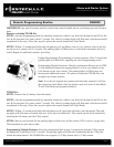
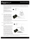
Firstech Shock Sensor
For best results mount the shock sensor by zip tying it to the vehicles main ignition harness. There is a small
dial on the sensor that ranges from Off to 10. The higher the number on the dial the greater sensitivity of impact.
A small adjustment to the dial can make a signicant difference in sensitivity for both 1st and 2nd stages. Rec-
ommended dial settings for most vehicles is somewhere between 2 & 4.
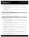
Siren
The volume output of the siren chirps can be increased 3 dB by cutting black wire loop located near the base of
the siren. To adjust duration time when the alarm has been triggered, change Option 3-07 – the system default is
30 seconds.
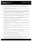
Thermister (Temperature Sensor)
Every 2 Way LCD Firstech RF kit includes an optional thermister, which must be plugged into the 2 pin port of
the control module for use. This plug is blue on the CM6000. The use of the thermister allows the 2 Way remote
to display the vehicle’s interior temperature on the remote LCD (liquid crystal display) as well as permitting the
vehicle to start with timed Hot or Cold starting; see options 2-05, 2-07 and 2-08. IMPORT
ANT: New thermister
plugs are blue 2 pin connectors on the CM6 series but old white plug thermistors will still work.
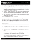
Hood Pin
The hood pin switch triggers the alarm in the event the hood is opened while the alarm is armed. The hood pin
also doubles as an important safety feature that prevents the remote start from engaging while the hood is open.
Backup Battery
The backup battery input on the control module / brain is for any optional battery backup unit (sold separately).
The red positive lead (+) acts both as an input and charging output for a 12 Volt battery backup. A backup
battery maintains basic alarm functionality when main vehicle power is lost. See the wiring schematic section
for complete details.
CM6000 Install Guide
Alarm and Starter System
www.firstechonline.com | www.compustar.com
Copyright 2009 Firstech, LLC.
Page 8
Common Procedures CM6000
Jumper Settings
Caution: Jumper settings affect the polarity and use of certain outputs. If these jumpers are used incorrectly,
damage to the vehicle and /or control module may occur.
Jumper 1 (Door Trigger Polarity)
Determines the polarity of the door trigger input wire (red/white). In the default position the door trigger
registers negative (-) triggers. To change to a positive (+) trigger, move the jumper.
Jumper 2 (Glow Plug or Key Sense Polarity)
Determines the polarity of the glow plug or key sense input wire (brown/white). In the default position it
monitors a positive (+) glow plug input. To change to a negative (-) input move the jumper. To change from the
glow plug to the key sense setting, you must change Option 4-09.